HVAC Ductwork Design Guide (Layout, Duct Size & CFM)
Designing HVAC ductwork requires experience and broad knowledge about ducted air conditioning. Some people want to learn how to design HVAC ductwork, especially for residential. So, I decided to try and walk them through.
Generally, duct design starts with identifying the airflow needed in each room. Then, we need to size and place the supply diffuser and return grille. After that, we can proceed to size the duct and design its path. Finally, we want to consider adding a fresh air duct and check the static pressure in the duct system.
But, before you can start the ductwork design for your home, you must first calculate the cooling capacity needed and thus, select a suitable HVAC unit. For sizing air conditioners, see my post Air Conditioner Sizing Guide: Sizing Chart (BTU & Ton).
Afterward, you need to decide what type of supply air diffuser you prefer and settle the size of the supply air diffuser. For that, you can see my post Supply Air Diffuser Sizing Guide (Practical Selection).
If you’re using conventional return air grilles, there is no performance datasheet for you to select from. Hence, you need to calculate the grille size using a formula which you can find from my post Return Air Grille Sizing Guide: CFM Chart & Calculation.
In addition, if you want to know the common options available for supply air diffusers and return air grilles before you decide which one to put in your home, see my posts as follow:
- 6 Types of Supply Air Diffusers and Their Applications
- 4 Types of Grilles in HVAC (Common Applications)
As you can see, designing HVAC ductwork is a lengthy process, especially if you have little to no knowledge about it. However, it is not impossible to design it by yourself.
Once you got the HVAC unit, diffuser and grille sorted out, get ready a layout plan drawing or sketch it out. You’ll be designing the ductwork on the drawing.
For me, I’ll be using the following layout drawing produced using AutoCAD as an example to show you exactly how to design HVAC ductwork for homes:
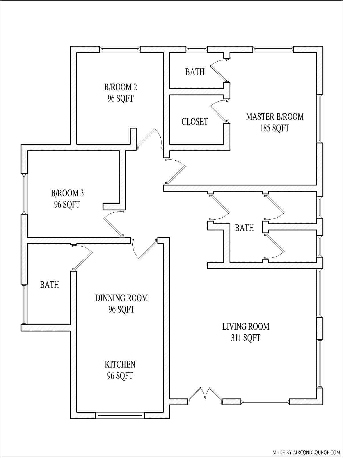
So, follow the below step-by-step process and I hope you will be able to design HVAC ductwork successfully. Let’s get started.
Note that this guide is part of my HVAC Beginner Course: 10 Days to Become Competent in HVAC. So, if you like to learn the basic design skills including this duct design, consider enrolling in the course. It’ll give you a head start.
1. Calculate the CFM for Each Room
Most HVAC units are designed to have a 400 CFM of airflow for every 12000 BTU or 1 ton of cooling capacity and 12000 BTU divided by 400 CFM is 30.
So, identify the BTU needed for each room and divide it by 30 to get the required CFM for the respective room.
Let’s say I have a single-storey house is equipped with a 30000 BTU ducted air conditioner with an airflow of 1000 CFM. The result of my CFM calculations are tabulated as follow:
| Room Name | Floor Area | Capacity Needed | Airflow |
|---|---|---|---|
| Living Room | 300 sqft | 9000 BTU | 300 CFM |
| Dining and Kitchen | 200 sqft | 9000 BTU | 300 CFM |
| Master Bedroom | 200 sqft | 6000 BTU | 200 CFM |
| Bedroom 2 | 100 sqft | 3000 BTU | 100 CFM |
| Bedroom 3 | 100 sqft | 3000 BTU | 100 CFM |
| Total | 900 sqft | 30000 BTU | 1000 CFM |
When indicated in the layout drawing, I have something like:
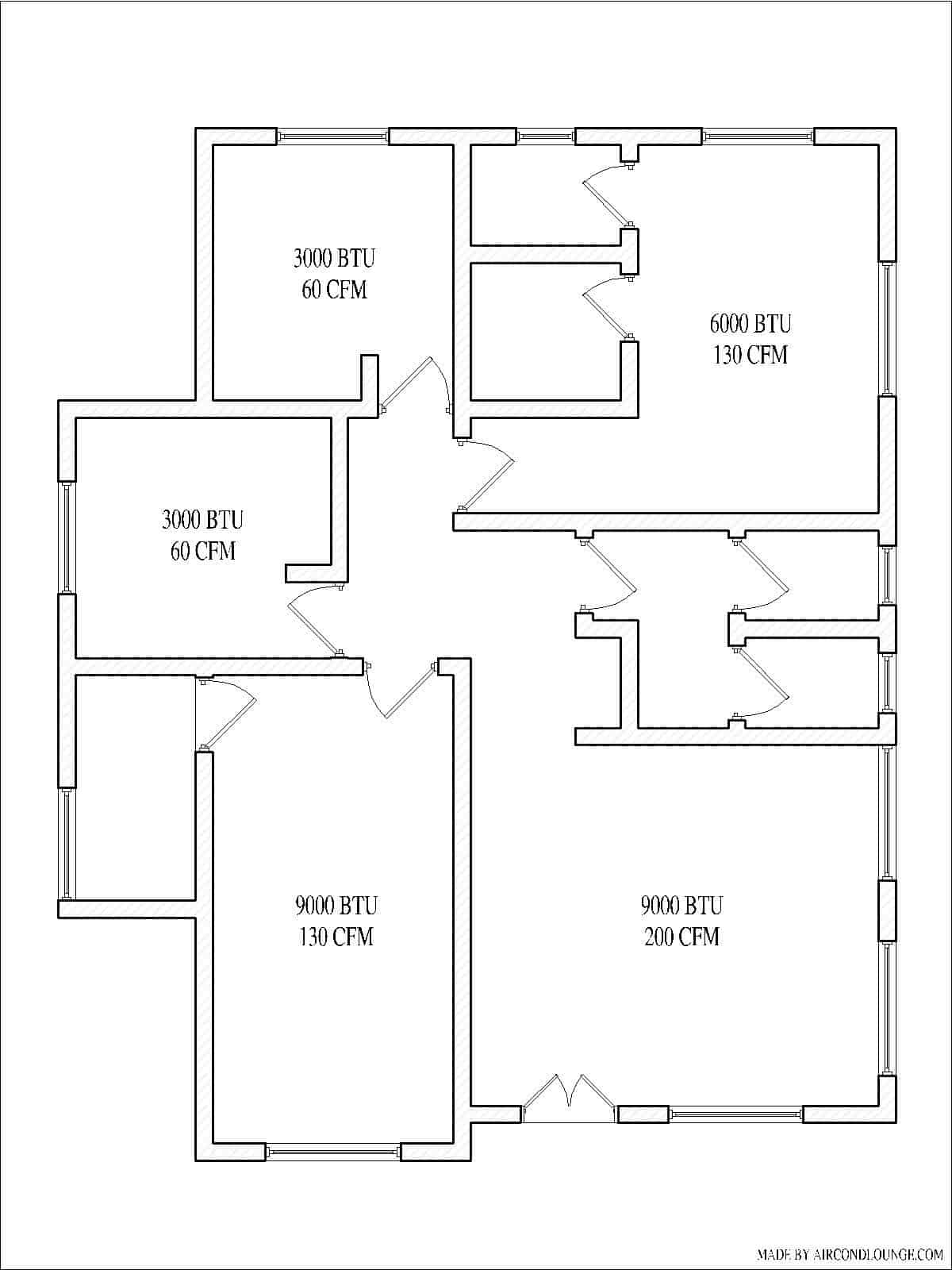
The living room has a floor area of 300 sqft and the capacity needed is 9000 BTU. To calculate the airflow requirement for the living room, divide 9000 BTU by 30 and the result is 300 CFM. Repeat the airflow calculation process for the rest of the room.
2. Design the Supply and Return Grille Location
The location of the supply and return grille determines how you will run the supply and return duct. So, draw the supply and return grille on your layout drawing.
As a reminder, you need to identify the size and type of the grille/diffuser before this step. Otherwise, you don’t know how many numbers of grille/diffuser you need for each room.
Generally, return air grilles should not be placed too close to supply air diffusers. Most of the time, you want the return grille to be at the opposite of the supply air diffuser.
Hence, air can flow from one side of the room to the other side of the room instead of short cycling itself which can lead to all sorts of cooling problems.
Also, you want to place the supply and return grille in symmetry so that they look good. Furthermore, try not to put any supply air diffuser too close to hot windows to avoid condensation.
Now, let’s continue with my example.
After I went through the diffuser selection process, I decided to use 2-slot 1200mm (48″) linear diffusers with a neck size of 150mm (6″) for both the supply air and the return air.
So, I updated the layout drawing as below:
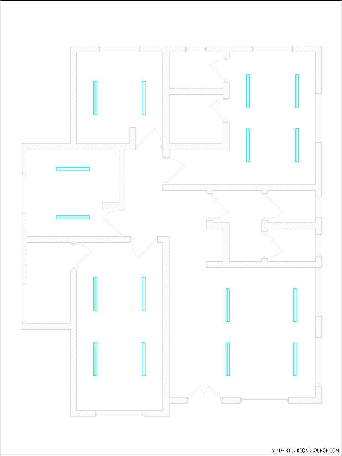
The living room needs 300 CFM of airflow. One supply air diffuser will probably do the job but I decided to go for two diffusers in an effort to reduce the noise level.
Also, I think that two diffusers look better for the living room.
Consequently, I also need two return air diffusers in order for the living room to look aligned as well as have sufficient return airflow.
So, there are a total of 4 linear diffusers in the living room.
Similarly, the dining and kitchen room has 4 linear diffusers and the master bedroom has 4 linear diffusers. Meanwhile, bedroom 2 and bedroom 3 only have 2 linear diffusers respectively.
3. Design the Supply Air Duct
Locate your HVAC unit and start by drawing the main duct first. Then, branch out the duct and extend it until it is close to the respective supply air diffuser.
The size of the main duct is based on the total airflow or the airflow rated on your HVAC unit. For duct sizing, you can use online calculators or see my post How to Calculate Duct Size? (Best Duct Size).
Whenever you branch out a duct, minus the total airflow by the airflow going to the branch duct to reduce the size of the subsequent main duct and connect two different duct sizes with a duct reducer.
As a general good practice, you should fix the height of the main duct to be about the same as the height of the HVAC unit. For instance, if your HVAC unit has a height of 250mm (10″), your main duct should also be 250mm (10″).
By guiding the height of the main duct, your ceiling height can be higher. Although square-shaped ducts are cheaper, they occupy more ceiling space and low ceiling height will make your home feel dark and cramped.
Keep in mind that you need to maintain a certain duct height regardless of the airflow. If you read my post on supply air diffuser sizing, you’ll understand why.
Basically, you need the duct to be tall enough to open a duct collar for a flexible duct connection. For instance, if the diffuser neck size is 150mm (6″), the flexible duct size is also 150mm (6″) and therefore, the duct height needs to be 200mm (8″) in order to fit the flexible duct.
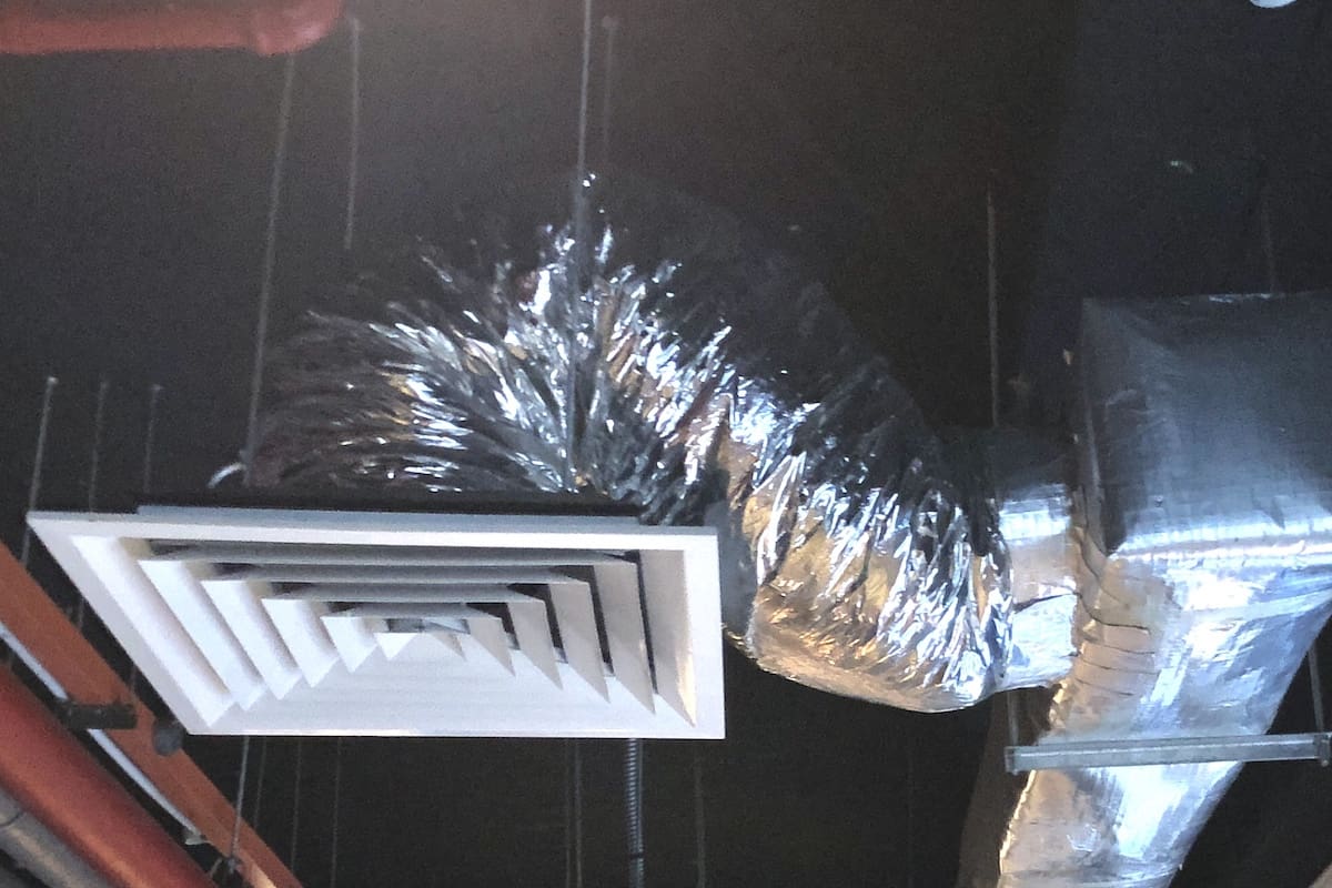
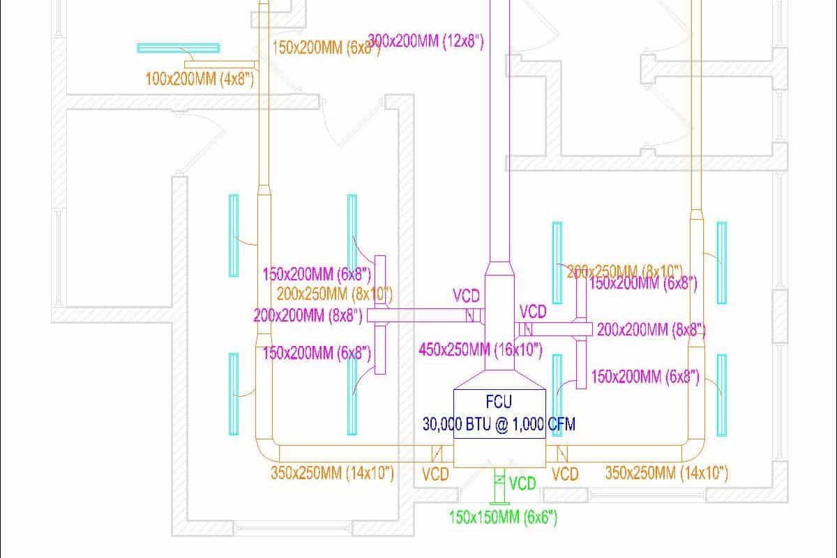
Now, let’s continue my example earlier. My HVAC unit is located above the ceiling in the living room. I extend the main duct and branch ducts as shown in the following layout drawing:
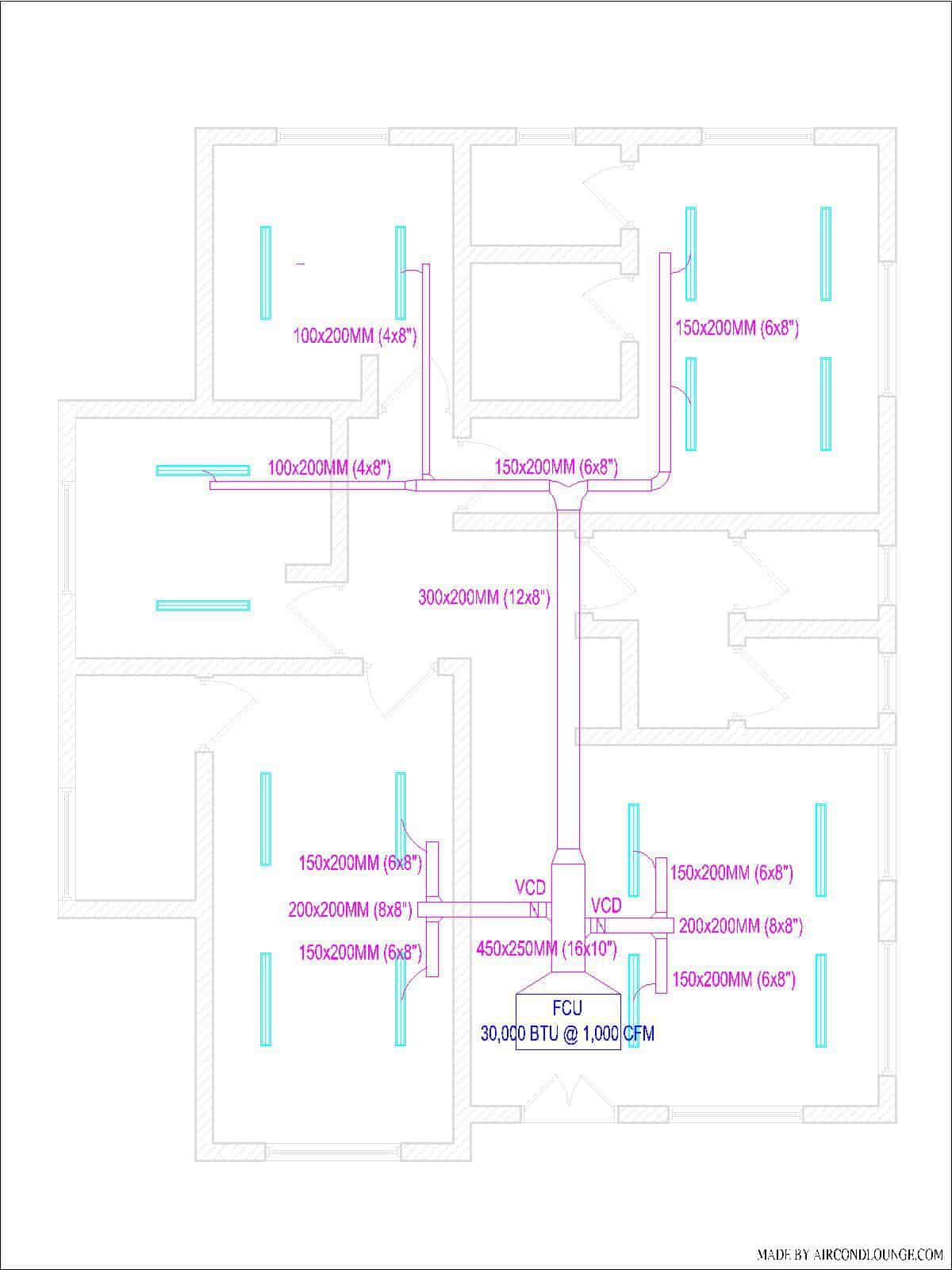
If you look closely, you’ll notice a little slope at each branch duct which indicates a guide vane is required for better airflow diversion from the main duct.
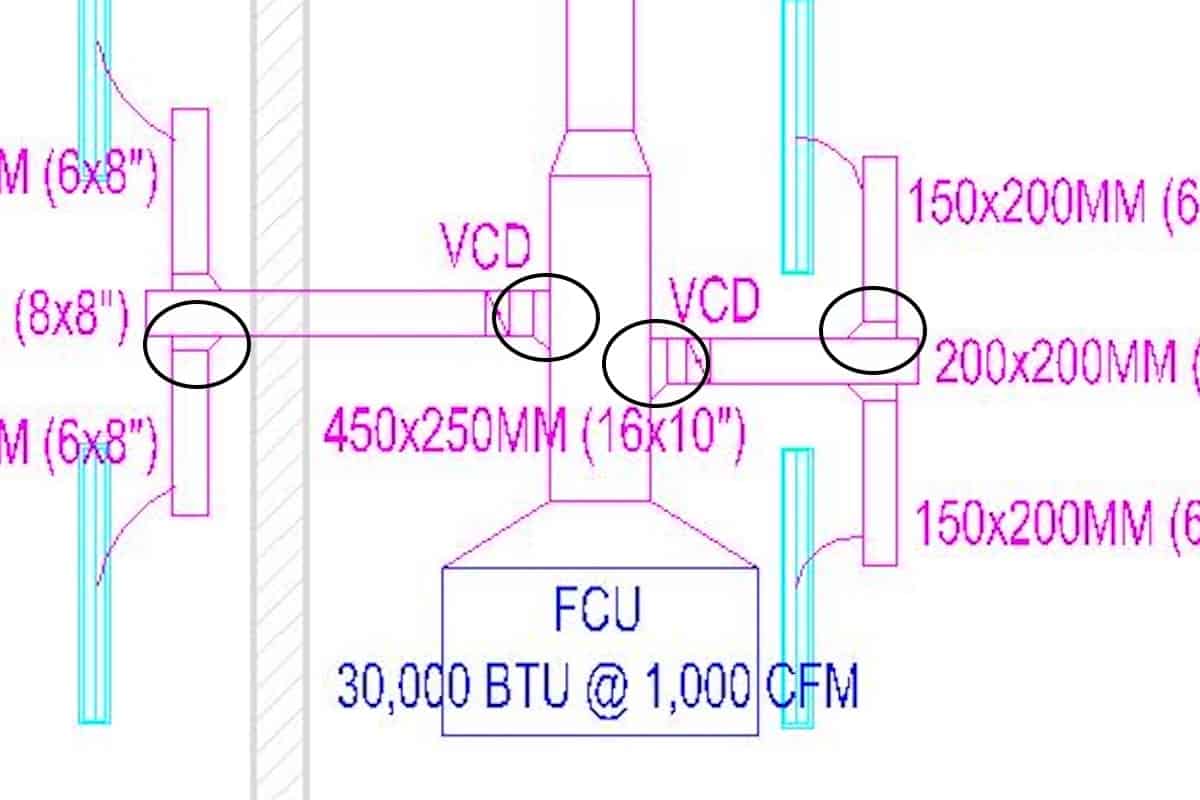
Guide vanes are important, especially for branch ducts that are close to the HVAC unit because the airflow is the strongest and it may blow past the branch duct, causing little to no airflow supply at the first few diffusers.
In addition, I included a volume control damper (VCD) at the first few duct branches to better control the airflow. Although each diffuser already has a damper, VCDs are still necessary to overcome strong airflow, especially near the HVAC unit.
Then, at the end of the branch duct, I use an end cap instead of a butterfly fitting. I prefer to use end caps because they are cheaper and faster to build. Meanwhile, butterfly fittings are better for airflow.
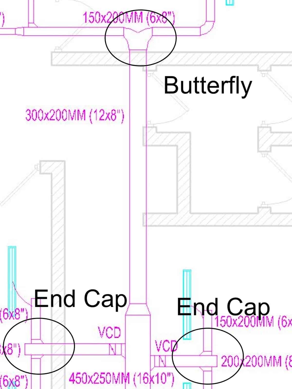
When the branch duct reaches the end, I draw a curve line connecting the diffuser to the duct, indicating a flexible duct connection.
Remember I mentioned earlier, all the diffuser neck size is 150mm (6″) and thus, all the flexible duct size is also 150mm (6″). Hence, I don’t really indicate the size in the layout drawing.
Once you are done with the main duct, branch ducts and flexible ducts, indicate their sizes on the layout drawing so that it is easier for you to request a quotation or do the costing.
4. Design the Return Air Duct
Follow the same procedure as the supply air duct to design the return air duct. You need to install a return air plenum box behind your HVAC unit to accommodate return duct connections.
However, if you are not dealing with multiple rooms, you may choose to use free return that doesn’t require any return duct. Basically, you use the space above the ceiling as a plenum for return air.
Otherwise, you need return air ducts and it is advisable to have a return air grille in each room. To understand why, see my post Does Every Bedroom Need a Cold Air Return Vent & Duct?.
Most of the time, central air conditioners in homes require ducted returns.
Now, back to my example. I have to use return air ducts because I use one HVAC unit for the entire home and thus, there are multiple rooms to serve.
Below is the updated layout drawing with return air ducts:
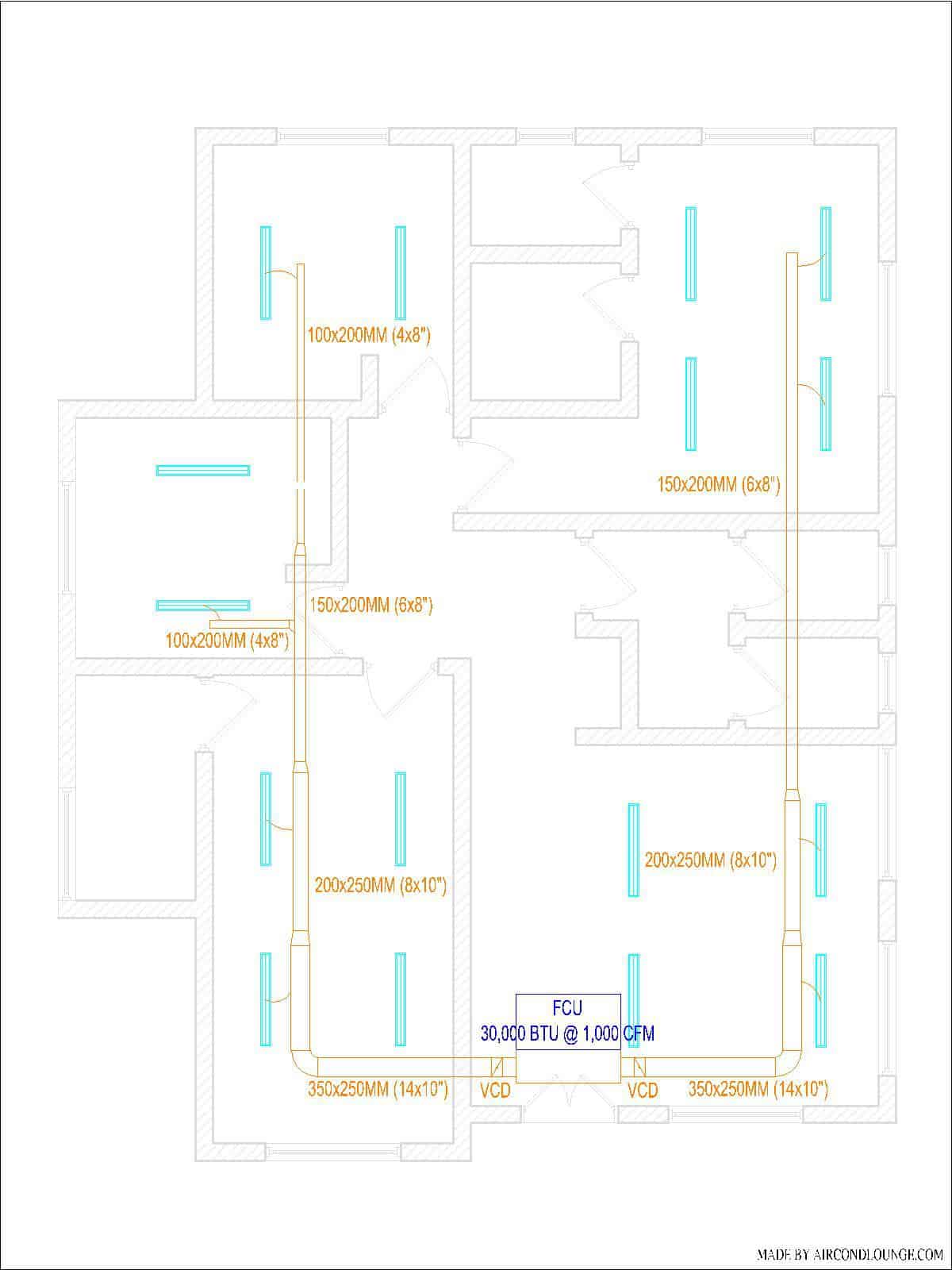
Similarly, I design the return air duct just like how I did for the supply air duct. However, I try not to let any return air duct intersect with the supply air duct because it requires much more ceiling space at the point where the duct crosses.
5. Design the Fresh Air Supply Duct
It is better to include a fresh air supply duct to introduce outdoor air for ventilation. Typically, the fresh air is about 10% of the total airflow of the HVAC unit.
So, find a suitable wall for the fresh air grille and connect a duct from the grille to the return air plenum box. If you’re using free return, a fresh air duct is not needed, just the fresh air grille.
Since fresh air grilles often don’t come with an airflow control damper, a volume control damper (VCD) is needed to limit the fresh air intake.
My HVAC unit is close to the exterior wall. So, I extended a fresh air duct from the return air plenum box to the wall as shown in the layout drawing as follow:
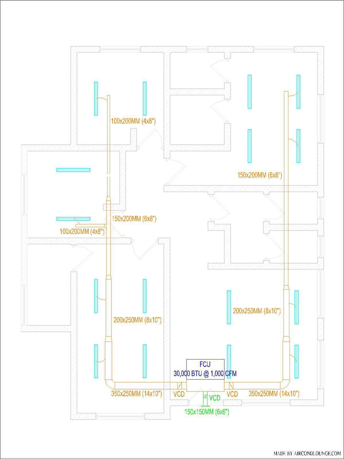
At this point, I pretty much completed the entire ductwork design. I have the supply, return and fresh air ducts as well as diffusers and dampers.
6. Check the External Static Pressure
Although you are most likely fine with the external static pressure, it is good to double check just in case you stretched the duct too long.
To calculate external static pressure, add the static loss of following duct components:
- Straight duct – 0.1 in.WG per 100 ft
- 90 degree elbow – equivalent to 16 ft of straight duct
- Grille and diffuser – 0.1 in.WG
Now, let’s take a look at my layout drawing as follow:
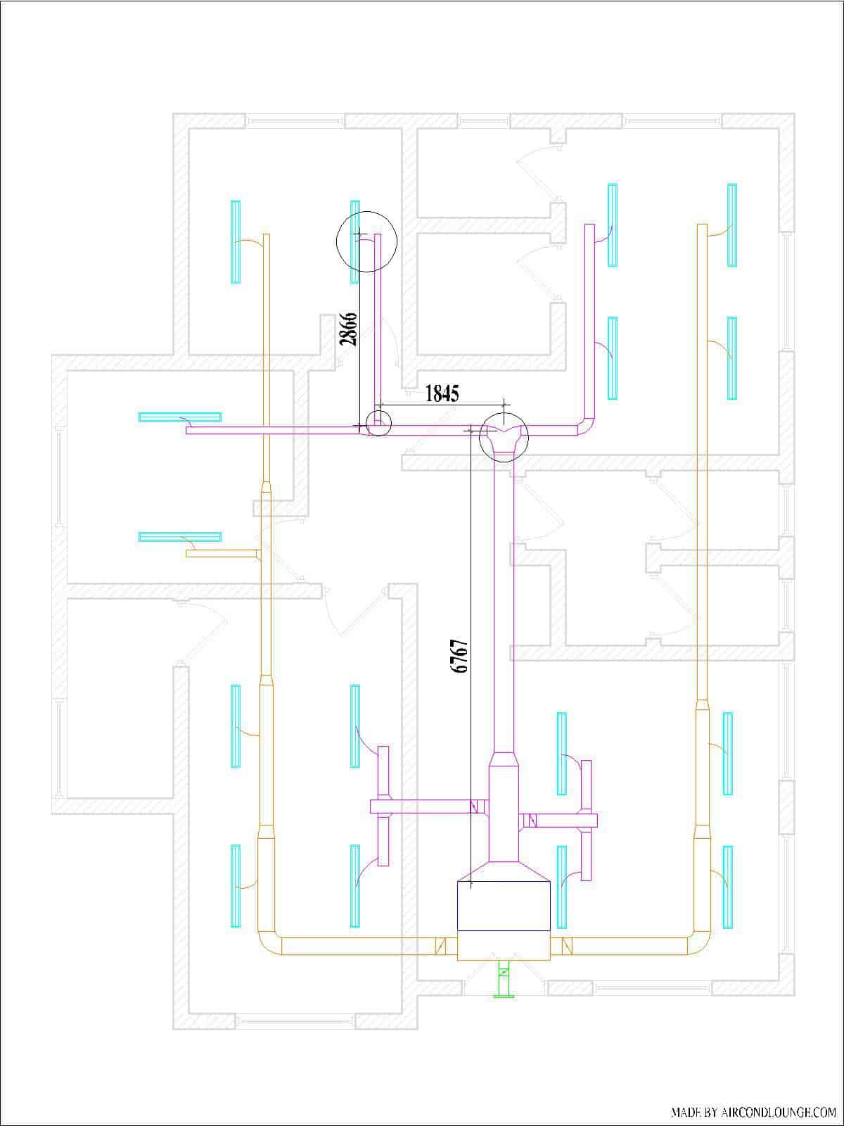
Take the longest route and measure the duct length. From the above layout drawing, the total static loss can be calculated as follow:
Straight Duct
Total length = 11478 mm or 38 ft.
Total static loss = 0.1 ÷ 100 x 38
Total static loss = 0.038 in.WG
90 Degree Elbow
Total quantity = 2 elbows
Total equivalent straight duct length = 2 x 16 = 32 ft
Total static loss = 0.1 ÷ 100 x 32
Total static loss = 0.032 in.WG
Since there is the end of the duct is a diffuser and the static loss of a diffuser (c/w plenum box) is 0.1 in.WG, the total static loss is 0.038 + 0.032 + 0.1 = 0.17 in.WG.
Most ducted air conditioners with 30000 BTU of cooling capacity have an external static pressure rating of 0.2 in.WG to 0.4 in.WG. Hence, we are fine with 0.17 in.WG.
In other words, we know that a 30000 BTU ducted air conditioner has a fan strong enough to push through 0.17 in.WG of friction and deliver air at the farthest supply air diffuser.
The above is the simplified method to calculate duct static pressure. To learn the full process, go to my post: How to Calculate Static Pressure in a Duct.
Finalization
By now, your layout drawing should be full of details. If I put together my ductwork design, it looks like the below layout drawing:
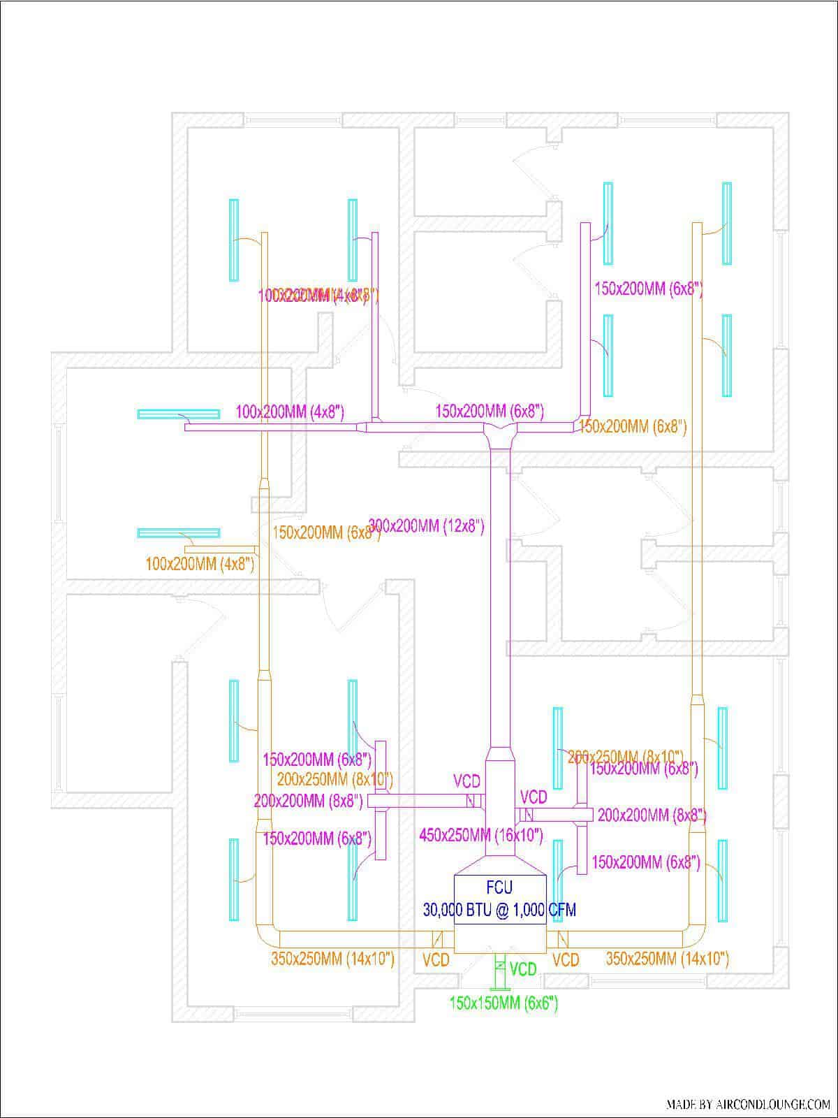
So, HVAC ductwork design has a few important elements to include:
- Duct size
- Volume control damper
- Guide vane
- Plenum box
- Fresh air intake
- Minimum duct height
Among all, the minimum duct height is the most critical element but is easily forgotten. If the duct height is not sufficient, workers will simply compress the duct collar in order to fit and connect the flexible duct. Consequently, you’ll have weak flexible duct joints which can cause air leakage problems in the future.
Guide vanes are also very important. Without them, you may not have a balanced airflow throughout your home. Meanwhile, your contractor should perform air balancing as well.
Relevant post: HVAC Air Balancing: Basics, Tools & Procedures.
Designing a good ductwork system requires broad HVAC knowledge. With the above steps and examples, I hope by now you can design the ductwork for your home.
If you have trouble or not feeling confident enough, consider my Email Consultation service or directly engage me to design the duct system with my Design & Layout Drawing. I’ll help you finish up your HVAC design in no time.
If you have anything to add (or ask) about this topic, leave a comment down below!


