Fire Damper Installation, Configuration and Joint Method
Fire dampers are one of the most critical components in HVAC. They prevent fire from spreading from one room to the other rooms. However, incorrect installation can lead to a fire damper malfunction and wrong configuration and joint method can hinder the inspection work.
Many engineers don’t pay enough attention to how their fire dampers are configured, connected and installed in wall and slab openings, leading to their fire dampers not doing what they’re supposed to do in critical situations.
Most of the time, the configuration, size and joint method of a fire damper are decided based on “as long as it fits into the duct”. Now, we should revisit how fire dampers are supposed to be installed.
What is a Fire Damper?
To understand why fire dampers should be installed in certain ways, we must first understand what is a fire damper and what it supposed to do.
In HVAC, large air conditioning ducts often need to penetrate through walls and slabs. We usually locate the air handling unit (AHU) in a dedicated room and run the duct toward the room that needs air conditioning. So, it is inevitable that one or more wall penetrations are required.
Whenever a duct penetrates through a wall, the penetration point which we call duct opening or wall opening, must have a fire damper.
In case of a fire outbreak, the fire damper will close to prevent the fire from spreading to the adjacent room. In fire protection, this is known as fire compartmentation.
So, most of the time, any wall penetration must have a fire damper, unless both rooms (before and after the penetration) are not a fire compartment.
If we’re dealing with offices, hotels and hospitals, fire dampers are certainly required.
Now, the concern is air conditioning ducts are usually not fire-rated. So, during a fire, they may collapse under the immense heat. If the fire damper is just slotted inside the duct, the collapse could pull the fire damper down, leaving a hole at the wall penetration point.
That’s why we need to make sure not just that there is a fire damper in the wall opening, but also that the fire damper is properly installed.
Fire Damper Installation in Wall Penetration
When a duct needs to penetrate through a wall, we typically make an opening about 50mm (2″) all-round wider than the duct size. For example, if the duct size is 1500x300mm, the wall opening size is 1600x400mm.
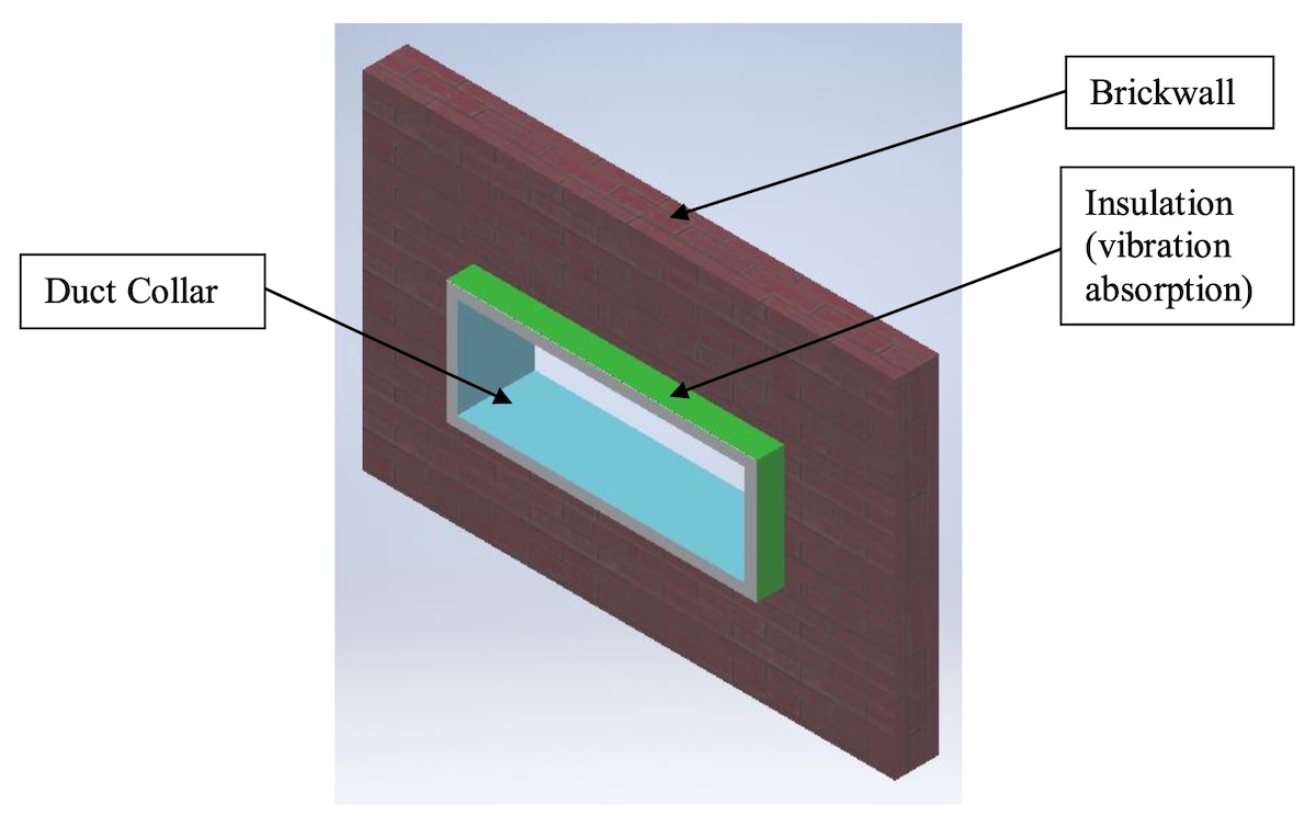
After the wall opening is done, we put a duct collar (sleeve) that’s already wrapped with a layer of insulation into the wall. The duct collar may not fit perfectly with some loose space but it’s fine because we can seal up the extra space with cement and stones later on.
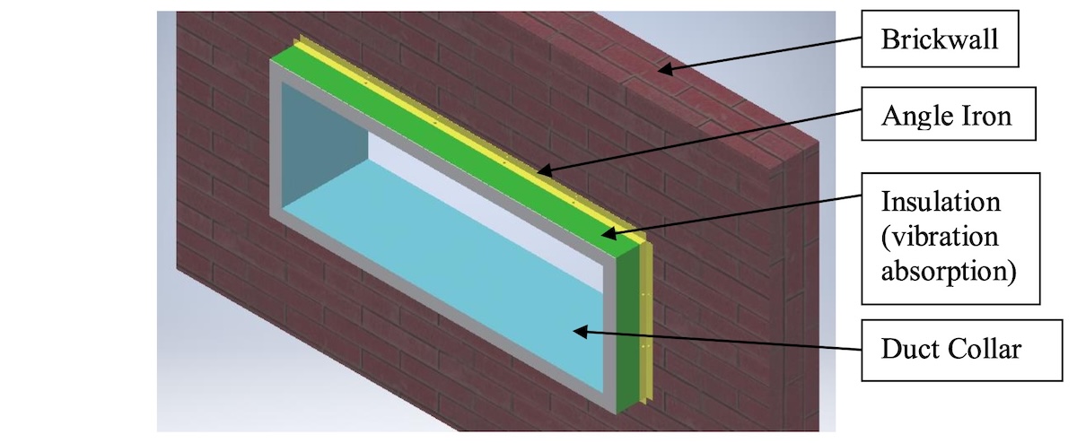
After that, we want to secure the duct collar onto the wall with angle irons. The angle irons should be bolted onto the duct collar on one side and bolted to the wall on the other side. That’ll make sure the duct collar stays intact on the wall.
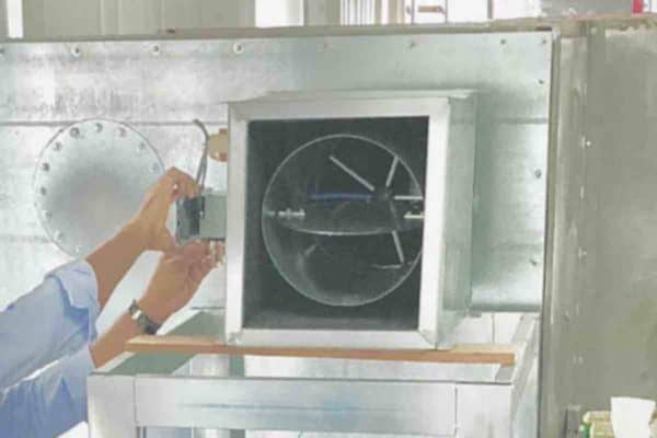
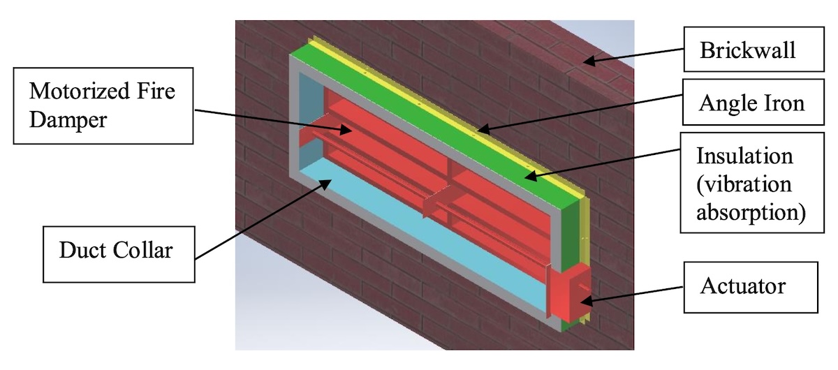
Next, we slot a fire damper into the duct collar. If we’re using a motorized damper, we need to make sure our damper actuator configuration is correct (more on that later).
Finally, we connect the duct on both sides. Here, it is also recommended to use a breakaway joint for the connection between the duct and the duct collar to further ensure that the duct collar alongside the fire damper won’t be pulled down in case the main duct collapses.
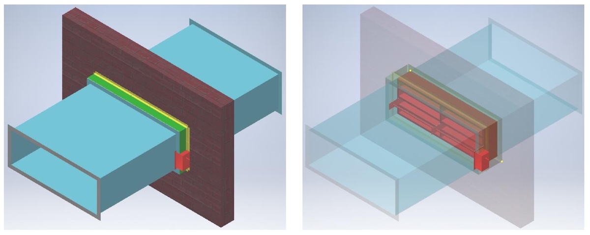
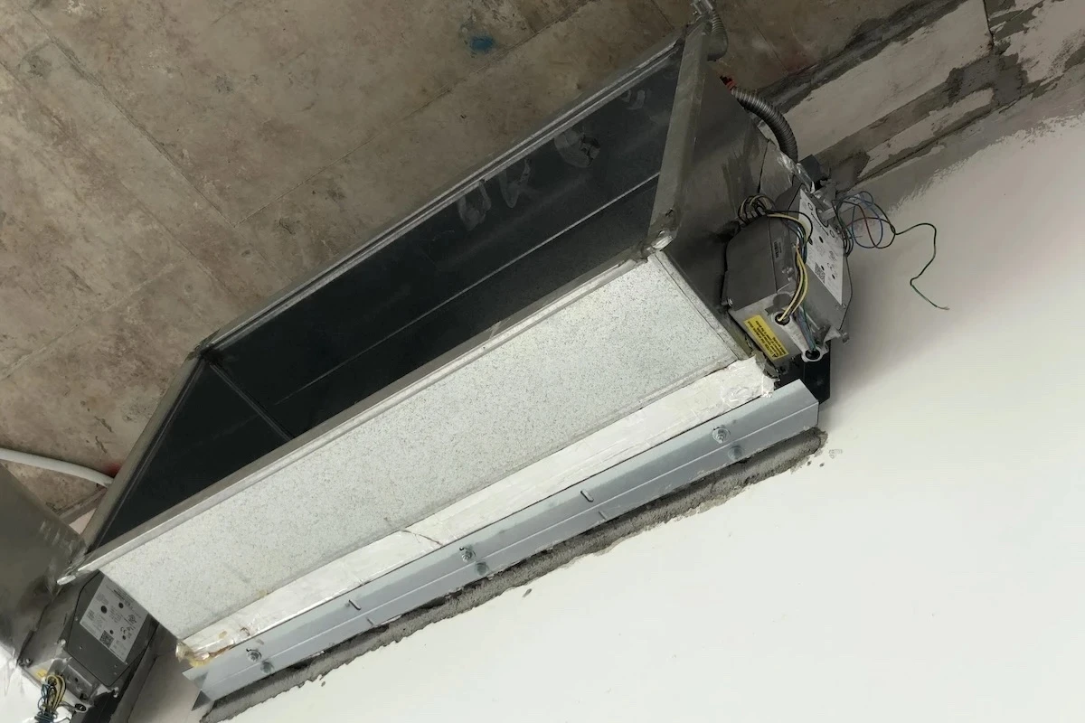
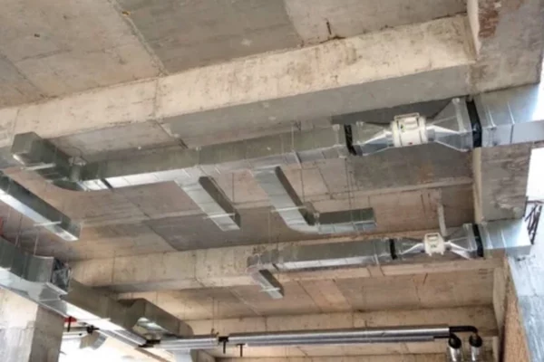
Here is how the fire damper and duct collar look when installed at the construction site. The angle irons have not yet bolted to the wall due to the opening has not been fully sealed and touched up.
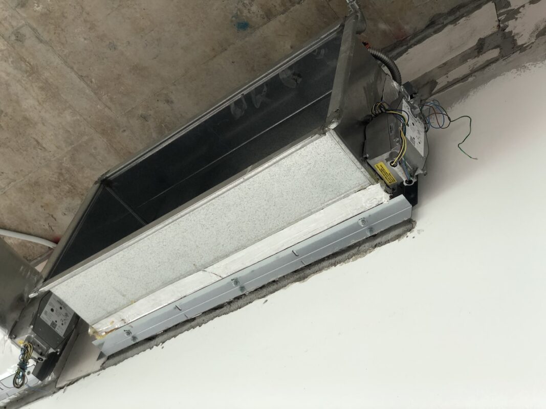
Here is what the motorized fire damper looks like when wrapped with a layer of insulation before slotting into the duct collar at the construction site.
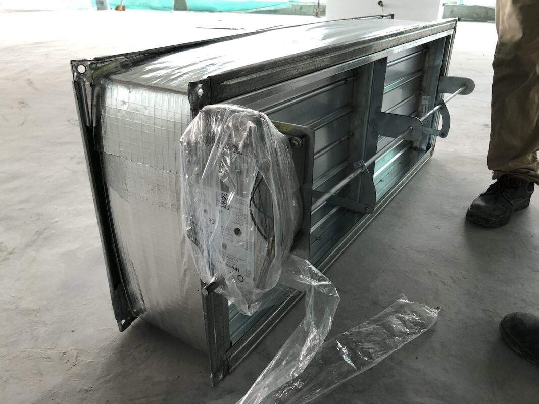
Previously, the workers did not understand how to install a fire damper in wall penetration properly and there was a bad practice in the installation of the fire damper. It took me a few months to get the sketches, 3D drawings, materials and mock-up installation done properly.
Motorized Fire Damper Configuration
Motorized fire dampers require us to configure how their actuator is mounted. Depending on where they’ll be installed, the configuration is different.
Here are the available configurations for motorized fire dampers. For my project, I need configurations A (shaft outside), D (inside middle) and F (infront shaft).
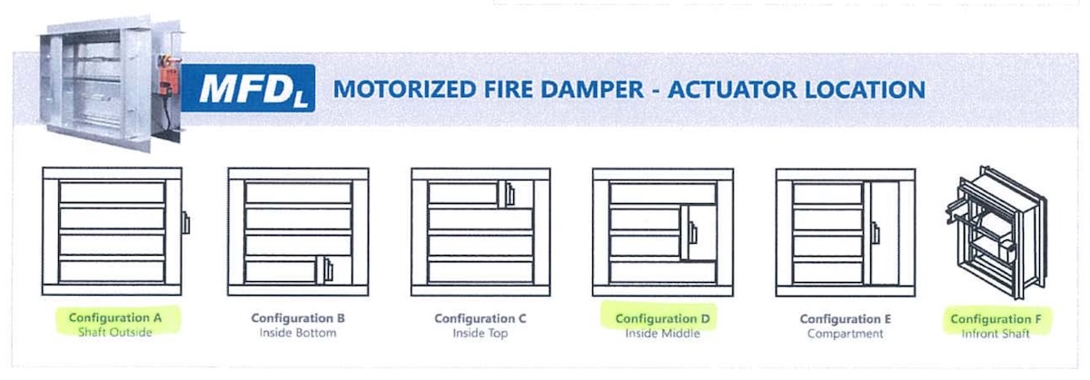
For wall penetration, configuration F is required because the other configurations will lead to the actuator not being able to be installed, inspected or replaced.
Configuration A which places the actuator on the side of the damper is obviously not suitable for wall penetration. Configuration D is possible but to access the actuator, we need to dismantle or go inside the duct. If the duct is wide enough and we have an access door on the duct, then it is feasible.
I found the easiest way to access the actuator is configuration F. By having the actuator outside the duct, we simply need to have a ceiling access manhole to be able to inspect or replace the actuator.
Configuration D is more suitable for corridor and staircase pressurization system where we can remove the front grille to reach the actuator.
In addition, we also can decide whether to put the actuator on the left or right side. This will depend on where it is more convenient to put the ceiling access manhole.
All these configurations and which side to put the actuator on must be finalized and submitted to the damper manufacturer for fabrication.
Fire Damper Joint Method
Whether it is a motorized or non-motorized (fusible link) fire damper, there are a few ways we can connect them to our air conditioning or ventilation ducts.

The easiest way is the TDC joint for large ducts and the slot in type for small ducts. In the case of my project, the angle joint is actually same as the slot in type but with additional angle irons and that’s what I was using previously.
Other types of joints lean more toward site conditions and requirements.
For slot in type, we don’t want to get exactly the same size as the duct. We want to deduct 10mm on all sides so that we have enough tolerance to slide in the damper at the site.
Key Takeaway
So, the important here is when a fire damper is going to be installed in wall penetration, it must be independently secured onto the wall to prevent the collapsed duct from taking it down. A breakaway joint can be used for the duct-damper connection to further enhance the integrity.
For motorized fire dampers, the configuration or the actuator position must be well planned such that there is sufficient space for installation and access for inspection and replacement in the future.
As for the joint method, dampers with the slot in type joint should be slightly smaller than the duct size to ensure smooth installation at the construction site.
Check out my digital products and online courses if you want to learn more about HVAC!
If you have anything to add (or ask) about this topic, leave a comment down below!


