How to Calculate Duct Size? (Round & Rectangular)
HVAC ducts are sized based on the required airflow. Undersized ducts can lead to all sorts of airflow problems. Some people like to use round ducts while others use rectangular ducts. So, how do you calculate the size of round ducts and rectangular ducts?
Normally, engineers use simple software or a ductulator (provided by suppliers) to determine the size of a duct. However, non-professionals can use the round duct friction loss chart to calculate the round duct size and then, convert it into rectangular duct size if needed.
Often, ducts require software to size. However, it can also be done without using any software or a ductulator but manually with the friction loss chart. So, let’s go through the process.
ASHRAE Duct Friction Loss Chart
To fully understand how to calculate duct size using the friction loss chart, I’ll quickly brief you through how to read the ASHRAE duct friction loss chart. Download the ASHRAE Duct Friction Loss Chart (IP & SI) here.
Friction Loss
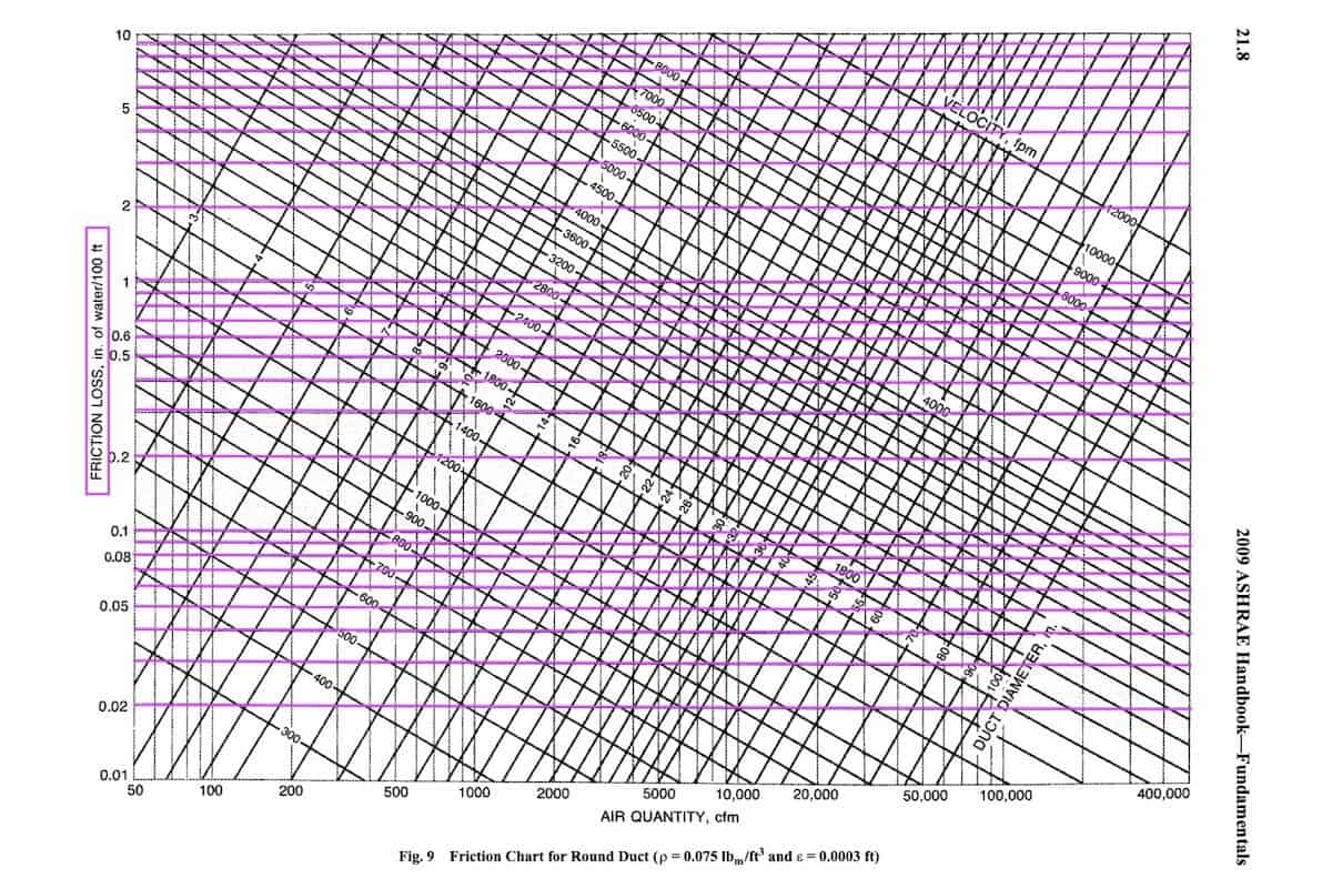
The horizontal lines on the duct friction loss chart is the friction loss of the duct, expressed in inches of water gauge (in.wg). It indicates the amount of friction resistance under different conditions. We don’t want the duct to experience too much of a friction loss because it requires more energy for the fan to push the air through the duct.
Generally, we practices a 0.1 in.wg of friction loss when sizing ducts. Low friction loss is good for energy savings but it’ll result in much larger duct sizes which increases the overall cost of the ducts.
Airflow
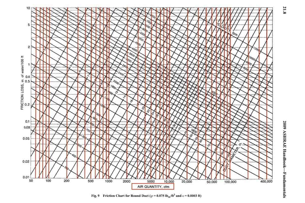
The vertical lines on the duct friction loss chart is the airflow, expressed in cubic feet per minute (cfm). This is the input from us as ducts are sized based on the airflow. The higher the airflow, the bigger the duct size.
Air Velocity
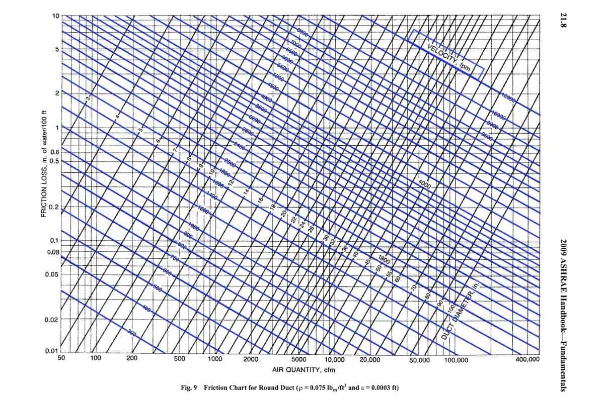
The right-diagonal lines on the duct friction loss chart is the air velocity, expressed in feet per minute (fpm). The air velocity represents the speed which the airflow is travelling inside the duct at different conditions.
Generally, we limit the air velocity at below 1500 fpm to control the noise level as the faster the air travels in the duct, the greater the noise.
Duct Size
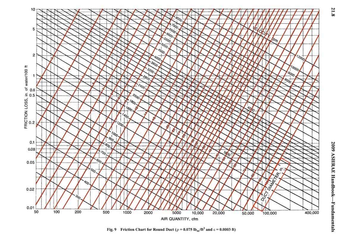
The left-diagonal lines on the duct friction loss chart is the size of round ducts in diameter (inches). Once we fixed the friction loss and air velocity, we can pull the airflow to match with the suitable duct diameter.
How to Calculate Duct Size?
Now that you know how to read the chart, the following is a step-by-step process on how to calculate duct size using the duct friction loss chart:
1. Fix the Friction Loss at 0.1 in.wg
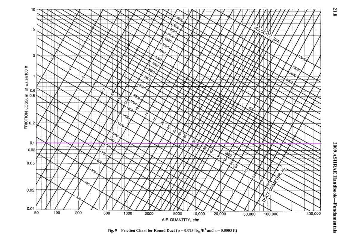
- Fix the friction loss at 0.1 in.wg.
- Low friction loss reduces the fan cost but increases the duct cost.
2. Fix the Air Velocity at 1500 fpm
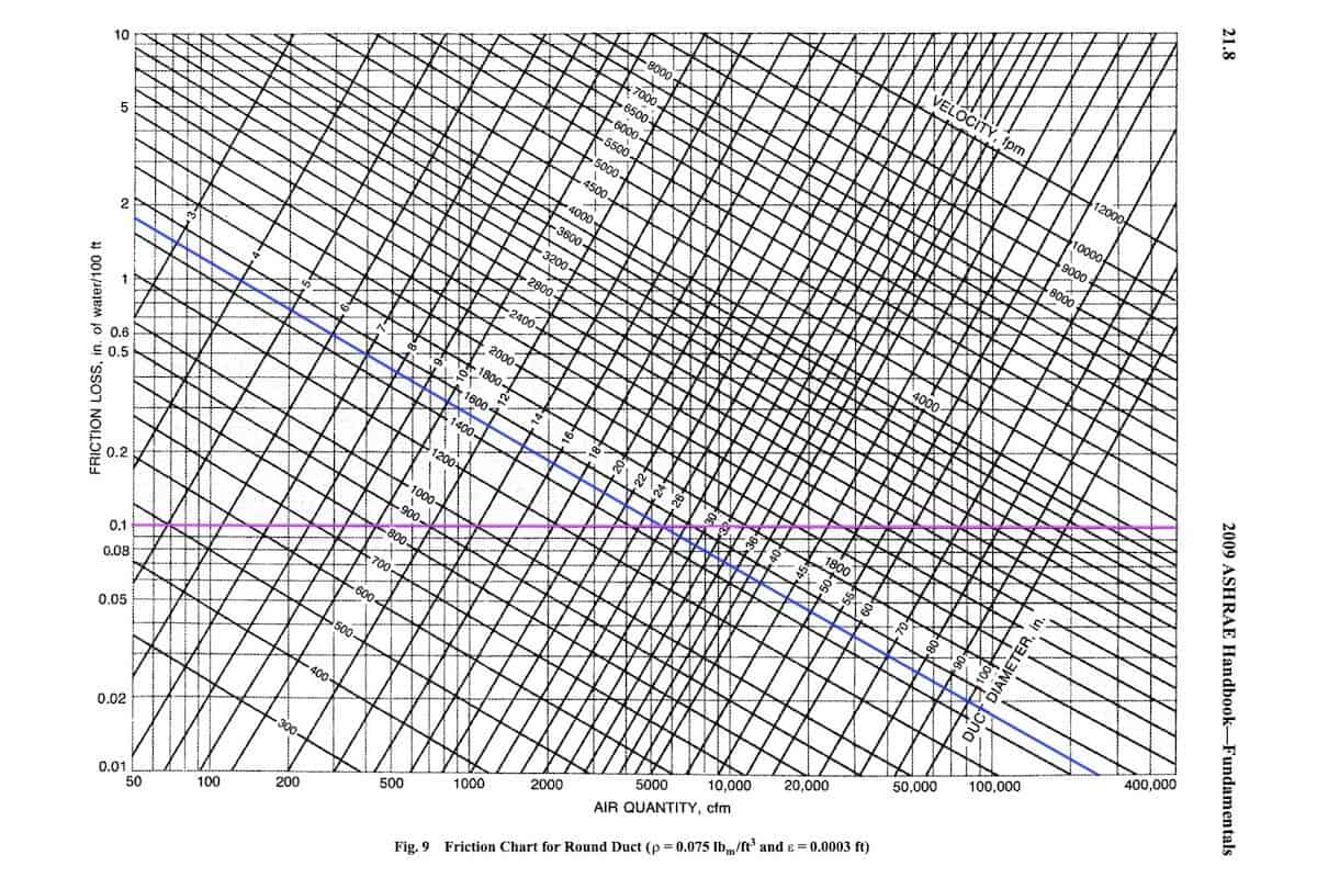
- Fix the air velocity at 1500 fpm.
- High air velocity reduces duct cost but increases noise level.
3. Use the Airflow to Find the Duct Diameter
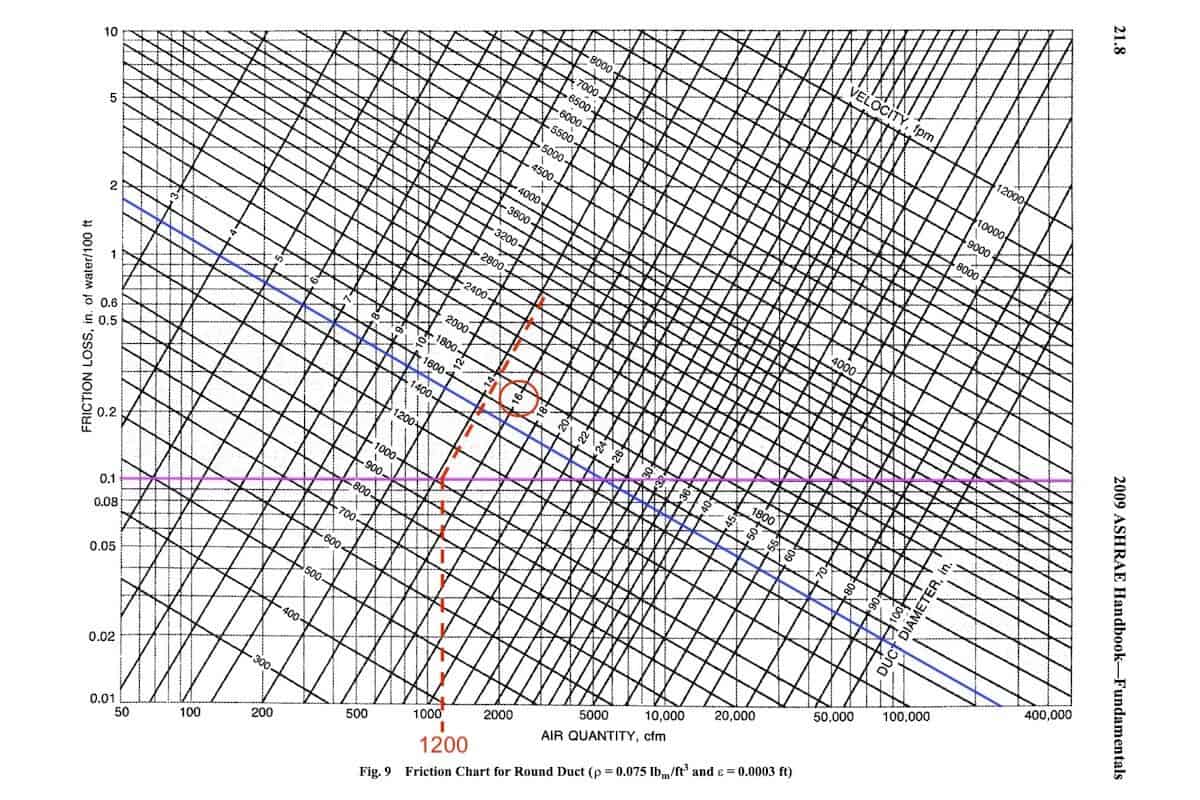
- Assume that the airflow is 1200 cfm.
- Pull the airflow vertically to hit the friction loss line at 0.1 in.wg. Then, pull the line diagonally to the right and find the suitable duct diameter.
- 14″ round duct is less than ideal because the friction loss will be greater than 0.1 in.wg as the maximum airflow for 14″ round ducts is around 1027 cfm.
- So, the suitable one is 16″ round duct.
4. Check the Air Velocity
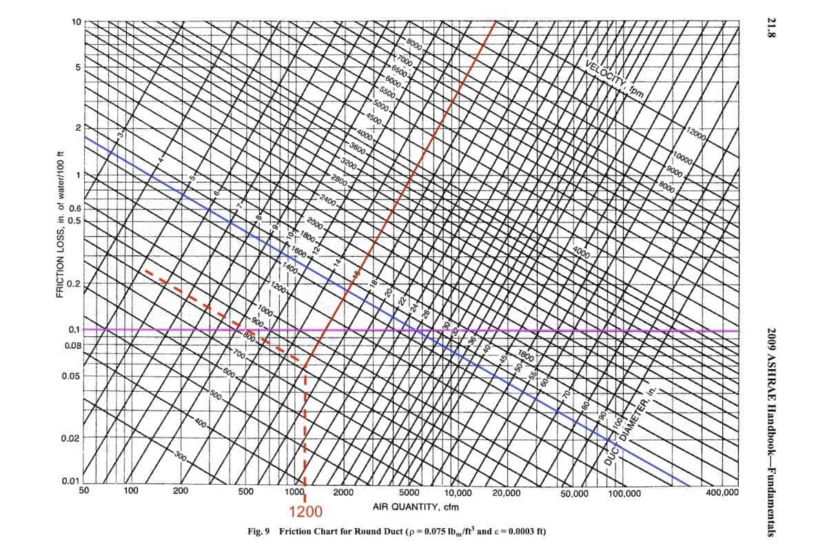
- Using 16″ round duct, pull the duct diameter line diagonally down to meet with the 1200 cfm vertical airflow line.
- Then, pull the line diagonally to the left to find the corresponding air velocity.
- In this case, the air velocity is around 830 fpm which is well under the 1500 fpm limit.
Air velocity usually is not a concern unless the airflow is approaching and exceeding 6000 cfm. Sometimes, a lower air velocity limit is recommended depending on local codes and guidelines. For example, ACCA Manual D suggests residential ductwork not exceeding 900 fpm.
By the way, you can speed up your design calculation process with my HVAC excel calculators. They are great for basic sizing and design. However, if you’re a design engineer, I encourage you to learn cooling load calculation as it is an extremely valuable skill to have.
RTS Cooling Load Calculation Course
Learn how to calculate cooling load using the ASHRAE’s Radiant Time Series method that accounts for solar heat gain, conductive heat gain, radiant heat gain and internal heat gain in a 24 hours load profile manner.
Round Duct CFM Chart
Now that you know how to calculate duct size manually. The following duct CFM chart can help you speed up the process. Just match the airflow with the duct size.
Design criteria:
- Friction Loss: ≤ 0.1 in.wg (0.816 Pa/m)
- Air Velocity: ≤ 1500 fpm (7.62 m/s)
See more duct CFM charts based on air velocity ≤ 900 fpm (ACCA Manual D).
| Duct Size | Airflow |
|---|---|
| 4″ (100mm) | 0 -35 cfm (0 – 60 m3/hr) |
| 6″ (150mm) | 36 – 107 cfm (61 – 182 m3/hr) |
| 8″ (200mm) | 108 – 231 cfm (183 – 393 m3/hr) |
| 10″ (250mm) | 232 – 419 cfm (394 – 712 m3/hr) |
| 12″ (300mm) | 420 – 682 cfm (713 – 1159 m3/hr) |
| 14″ (350mm) | 683 – 1027 cfm (1160 – 1746 m3/hr) |
| 16″ (400mm) | 1028 – 1463 cfm (1747 – 2487 m3/hr) |
| 18″ (450mm) | 1464 – 1999 cfm (2488 – 3398 m3/hr) |
| 20″ (500mm) | 2000 – 2641 cfm (3399 – 4490 m3/hr) |
| 22″ (550mm) | 2642 – 3398 cfm (4491 – 5777 m3/hr) |
| 24″ (600mm) | 3399 – 4275 cfm (5778 – 7268 m3/hr) |
| 26″ (650mm) | 4276 – 5280 cfm (7269 – 8976 m3/hr) |
| 28″ (700mm) | 5281 – 6414 cfm (8977 – 10904 m3/hr) |
| 30″ (750mm) | 6415 – 7363 cfm (10905 – 12517 m3/hr) |
Round to Rectangular Duct Conversion Chart
Round ducts and rectangular ducts are sized differently. Simply use the same duct area to convert from round to rectangular ducts is often inaccurate. So, I calculated the equivalent duct diameter for each rectangular duct sizes as follow:
| Round Duct | Equivalent Rectangular Duct |
|---|---|
| 4″ (100mm) | 4″ x 4″ (100 x 100mm) |
| 4″ (100mm) | 4″ x 6″ (100 x 150mm) |
| 6″ (150mm) | 4″ x 8″ (100 x 200mm) |
| 6″ (150mm) | 4″ x 10″ (100 x 250mm) |
| 6″ (150mm) | 4″ x 12″ (100 x 300mm) |
| 6″ (150mm) | 4″ x 14″ (100 x 350mm) |
| 6″ (150mm) | 6″ x 6″ (150 x 150mm) |
| 6″ (150mm) | 6″ x 8″ (150 x 200mm) |
| 8″ (200mm) | 4″ x 16″ (100 x 400mm) |
| 8″ (200mm) | 6″ x 10″ (150 x 250mm) |
| 8″ (200mm) | 6″ x 12″ (150 x 300mm) |
| 8″ (200mm) | 6″ x 14″ (150 x 350mm) |
| 8″ (200mm) | 8″ x 8″ (200 x 200mm) |
| 8″ (200mm) | 8″ x 10″ (200 x 250mm) |
| 10″ (250mm) | 6″ x 16″ (150 x 400mm) |
| 10″ (250mm) | 6″ x 18″ (150 x 450mm) |
| 10″ (250mm) | 6″ x 20″ (150 x 500mm) |
| 10″ (250mm) | 6″ x 22″ (150 x 550mm) |
| 10″ (250mm) | 8″ x 12″ (200 x 300mm) |
| 10″ (250mm) | 8″ x 14″ (200 x 350mm) |
| 10″ (250mm) | 10″ x 10″ (250 x 250mm) |
| 10″ (250mm) | 10″ x 12″ (250 x 300mm) |
| 12″ (300mm) | 6″ x 24″ (150 x 600mm) |
| 12″ (300mm) | 8″ x 16″ (200 x 400mm) |
| 12″ (300mm) | 8″ x 18″ (200 x 450mm) |
| 12″ (300mm) | 8″ x 20″ (200 x 500mm) |
| 12″ (300mm) | 10″ x 14″ (250 x 350mm) |
| 12″ (300mm) | 10″ x 16″ (250 x 400mm) |
| 12″ (300mm) | 12″ x 12″ (300 x 300mm) |
| 14″ (350mm) | 8″ x 22″ (200 x 550mm) |
| 14″ (350mm) | 8″ x 24″ (200 x 600mm) |
| 14″ (350mm) | 8″ x 26″ (200 x 650mm) |
| 14″ (350mm) | 8″ x 28″ (200 x 700mm) |
| 14″ (350mm) | 10″ x 18″ (250 x 450mm) |
| 14″ (350mm) | 10″ x 20″ (250 x 500mm) |
| 14″ (350mm) | 10″ x 22″ (250 x 550mm) |
| 14″ (350mm) | 12″ x 14″ (300 x 350mm) |
| 14″ (350mm) | 12″ x 16″ (300 x 400mm) |
| 14″ (350mm) | 12″ x 18″ (300 x 450mm) |
| 14″ (350mm) | 14″ x 14″ (350 x 350mm) |
| 16″ (400mm) | 8″ x 30″ (200 x 750mm) |
| 16″ (400mm) | 8″ x 32″ (200 x 800mm) |
| 16″ (400mm) | 10″ x 24″ (250 x 600mm) |
| 16″ (400mm) | 10″ x 26″ (250 x 650mm) |
| 16″ (400mm) | 10″ x 28″ (250 x 700mm) |
| 16″ (400mm) | 12″ x 20″ (300 x 500mm) |
| 16″ (400mm) | 12″ x 22″ (300 x 550mm) |
| 16″ (400mm) | 14″ x 16″ (350 x 400mm) |
| 16″ (400mm) | 14″ x 18″ (350 x 450mm) |
| 18″ (450mm) | 10″ x 30″ (250 x 750mm) |
| 18″ (450mm) | 10″ x 32″ (250 x 800mm) |
| 18″ (450mm) | 10″ x 34″ (250 x 850mm) |
| 18″ (450mm) | 10″ x 36″ (250 x 900mm) |
| 18″ (450mm) | 12″ x 24″ (300 x 600mm) |
| 18″ (450mm) | 12″ x 26″ (300 x 650mm) |
| 18″ (450mm) | 12″ x 28″ (300 x 700mm) |
| 18″ (450mm) | 14″ x 20″ (350 x 500mm) |
| 18″ (450mm) | 14″ x 22″ (350 x 550mm) |
| 18″ (450mm) | 14″ x 24″ (350 x 600mm) |
| 18″ (450mm) | 16″ x 18″ (400 x 450mm) |
| 18″ (450mm) | 16″ x 20″ (400 x 500mm) |
| 18″ (450mm) | 18″ x 18″ (450 x 450mm) |
| 20″ (500mm) | 10″ x 38″ (250 x 950mm) |
| 20″ (500mm) | 10″ x 40″ (250 x 1000mm) |
| 20″ (500mm) | 12″ x 30″ (300 x 750mm) |
| 20″ (500mm) | 12″ x 32″ (300 x 800mm) |
| 20″ (500mm) | 12″ x 34″ (300 x 850mm) |
| 20″ (500mm) | 12″ x 36″ (300 x 900mm) |
| 20″ (500mm) | 14″ x 26″ (350 x 650mm) |
| 20″ (500mm) | 14″ x 28″ (350 x 700mm) |
| 20″ (500mm) | 16″ x 22″ (400 x 550mm) |
| 20″ (500mm) | 16″ x 24″ (400 x 600mm) |
| 20″ (500mm) | 18″ x 20″ (450 x 500mm) |
| 20″ (500mm) | 18″ x 22″ (450 x 550mm) |
| 20″ (500mm) | 20″ x 20″ (500 x 500mm) |
| Round Duct | Equivalent Rectangular Duct |
|---|---|
| 22″ (550mm) | 12″ x 38″ (300 x 950mm) |
| 22″ (550mm) | 12″ x 40″ (300 x 1000mm) |
| 22″ (550mm) | 12″ x 42″ (300 x 1050mm) |
| 22″ (550mm) | 12″ x 44″ (300 x 1100mm) |
| 22″ (550mm) | 14″ x 30″ (350 x 750mm) |
| 22″ (550mm) | 14″ x 32″ (350 x 800mm) |
| 22″ (550mm) | 14″ x 34″ (350 x 850mm) |
| 22″ (550mm) | 14″ x 36″ (350 x 900mm) |
| 22″ (550mm) | 16″ x 26″ (400 x 650mm) |
| 22″ (550mm) | 16″ x 28″ (400 x 700mm) |
| 22″ (550mm) | 16″ x 30″ (400 x 750mm) |
| 22″ (550mm) | 18″ x 24″ (450 x 600mm) |
| 22″ (550mm) | 18″ x 26″ (450 x 650mm) |
| 22″ (550mm) | 20″ x 22″ (500 x 550mm) |
| 22″ (550mm) | 20″ x 24″ (500 x 600mm) |
| 24″ (600mm) | 12″ x 46″ (300 x 1150mm) |
| 24″ (600mm) | 12″ x 48″ (300 x 1200mm) |
| 24″ (600mm) | 14″ x 38″ (350 x 950mm) |
| 24″ (600mm) | 14″ x 40″ (350 x 1000mm) |
| 24″ (600mm) | 14″ x 42″ (350 x 1050mm) |
| 24″ (600mm) | 16″ x 32″ (400 x 800mm) |
| 24″ (600mm) | 16″ x 34″ (400 x 850mm) |
| 24″ (600mm) | 16″ x 36″ (400 x 900mm) |
| 24″ (600mm) | 18″ x 28″ (450 x 700mm) |
| 24″ (600mm) | 18″ x 30″ (450 x 750mm) |
| 24″ (600mm) | 18″ x 32″ (450 x 800mm) |
| 24″ (600mm) | 20″ x 26″ (500 x 650mm) |
| 24″ (600mm) | 20″ x 28″ (500 x 700mm) |
| 24″ (600mm) | 22″ x 22″ (550 x 550mm) |
| 24″ (600mm) | 22″ x 24″ (550 x 600mm) |
| 26″ (650mm) | 14″ x 44″ (350 x 1100mm) |
| 26″ (650mm) | 14″ x 46″ (350 x 1150mm) |
| 26″ (650mm) | 14″ x 48″ (350 x 1200mm) |
| 26″ (650mm) | 14″ x 50″ (350 x 1250mm) |
| 26″ (650mm) | 16″ x 38″ (400 x 950mm) |
| 26″ (650mm) | 16″ x 40″ (400 x 1000mm) |
| 26″ (650mm) | 16″ x 42″ (400 x 1050mm) |
| 26″ (650mm) | 18″ x 34″ (450 x 850mm) |
| 26″ (650mm) | 18″ x 36″ (450 x 900mm) |
| 26″ (650mm) | 20″ x 30″ (500 x 750mm) |
| 26″ (650mm) | 20″ x 32″ (500 x 800mm) |
| 26″ (650mm) | 22″ x 26″ (550 x 650mm) |
| 26″ (650mm) | 22″ x 28″ (550 x 700mm) |
| 26″ (650mm) | 24″ x 24″ (600 x 600mm) |
| 26″ (650mm) | 24″ x 26″ (600 x 650mm) |
| 28″ (700mm) | 14″ x 52″ (350 x 1300mm) |
| 28″ (700mm) | 14″ x 54″ (350 x 1350mm) |
| 28″ (700mm) | 14″ x 56″ (350 x 1400mm) |
| 28″ (700mm) | 16″ x 44″ (400 x 1100mm) |
| 28″ (700mm) | 16″ x 46″ (400 x 1150mm) |
| 28″ (700mm) | 16″ x 48″ (400 x 1200mm) |
| 28″ (700mm) | 18″ x 38″ (450 x 950mm) |
| 28″ (700mm) | 18″ x 40″ (450 x 1000mm) |
| 28″ (700mm) | 18″ x 42″ (450 x 1050mm) |
| 28″ (700mm) | 20″ x 34″ (500 x 850mm) |
| 28″ (700mm) | 20″ x 36″ (500 x 900mm) |
| 28″ (700mm) | 22″ x 30″ (550 x 750mm) |
| 28″ (700mm) | 22″ x 32″ (550 x 800mm) |
| 28″ (700mm) | 24″ x 28″ (600 x 700mm) |
| 28″ (700mm) | 24″ x 30″ (600 x 750mm) |
| 28″ (700mm) | 26″ x 26″ (650 x 650mm) |
| 28″ (700mm) | 26″ x 28″ (650 x 700mm) |
| 30″ (750mm) | 16″ x 50″ (400 x 1250mm) |
| 30″ (750mm) | 18″ x 44″ (450 x 1100mm) |
| 30″ (750mm) | 20″ x 38″ (500 x 950mm) |
| 30″ (750mm) | 22″ x 34″ (550 x 850mm) |
| 30″ (750mm) | 24″ x 32″ (600 x 800mm) |
| 30″ (750mm) | 26″ x 30″ (650 x 750mm) |
| 30″ (750mm) | 28″ x 38″ (700 x 700mm) |
For the conversion between round ducts and rectangular ducts, the friction loss must maintain at 0.1 in.wg and below. Then, the air velocity is also limited at 1500 fpm and below. Next, the rectangular duct ratio must not exceed 1:4. Finally, the maximum airflow must be the same for both round ducts and rectangular ducts.
Calculate Duct Size Using a Ductulator
When I first started working as a fresh-graduate project engineer, my manager gave me a ductulator. It is round in shape with many words and numbers written on it. It has a mechanism that allows its middle part to rotate which gives us the duct sizes based on a few parameters.
I still remember that the ductulator is made by Trane. It looks something like this on Amazon but the Amazon one is way better than mine. After all, it was more than 7 years ago since I had my ductulator.
The ductulator I had was a used one with a few markings on it. Particularly, the friction (head) loss was marked at 0.1. I was told that engineers generally use a friction loss of 0.1 in.wg per 100 ft (0.816 Pa per meter) when sizing ducts.
With a ductulator, all you have to do is mark the friction loss at 0.1 in.wg per 100 ft (0.816 Pa per meter) and then rotate your airflow until it aligns with the marked friction loss (blue color section). Then, you see the bottom part of the ductulator to find the rectangular duct size (green color section).
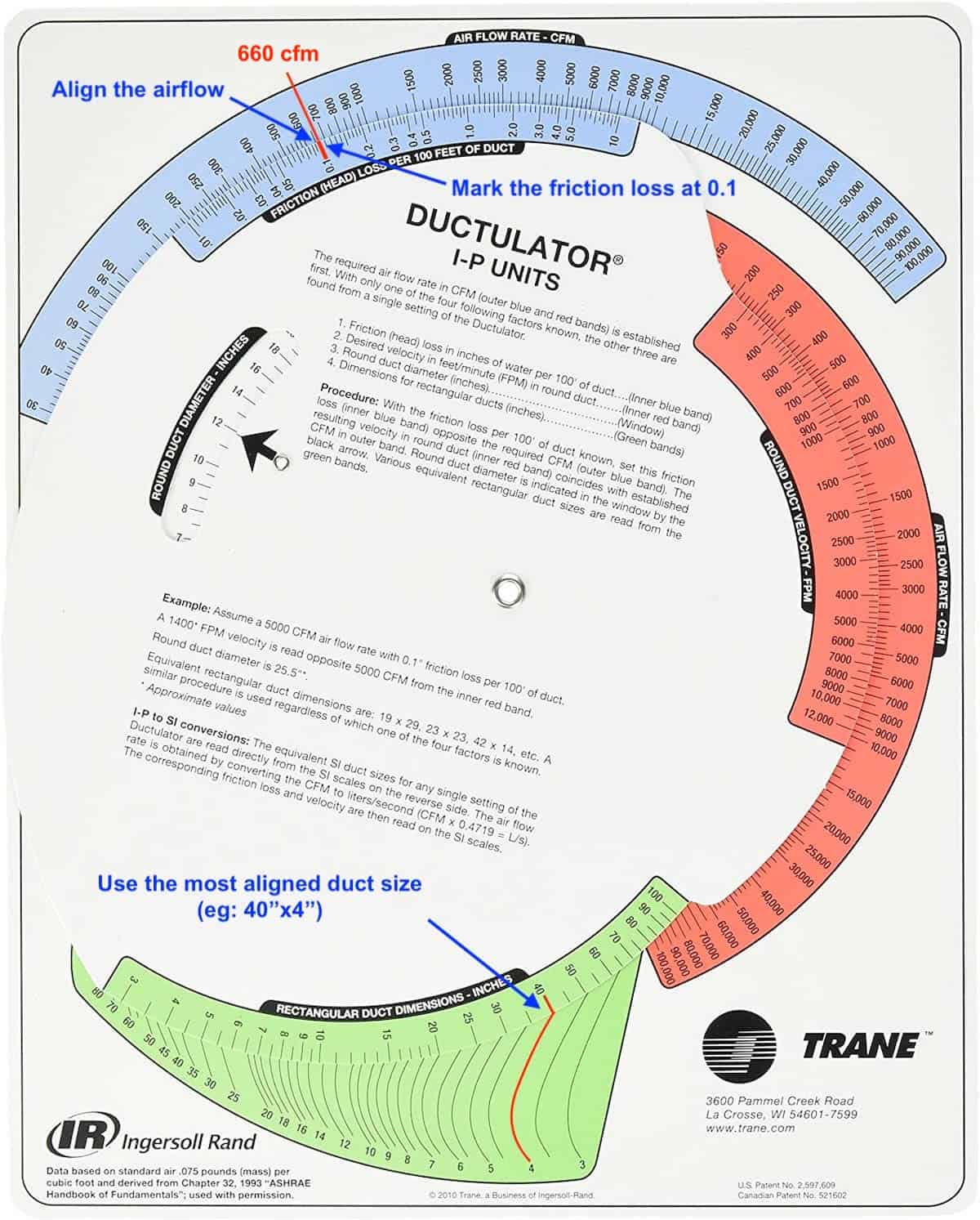
You always want to use the most aligned duct sizes because they fit the best for that airflow. A not-so-align duct size such as 30″x5″ is considered slightly oversized/undersized and not optimal in terms of the cost.
As you might have noticed, there are many different duct sizes to choose from. Later, I’ll guide you on how to select the best duct size.
For round ducts, it is very straightforward. It will be displayed at the round duct section (white color section) as you rotate the ductulator. But, you might want to check the air velocity (orange color section) if you’re using round ducts.
Calculate Duct Size Using Software
After about 3 years of working, one of my seniors gave me a softcopy ductulator called McQuay Duct Sizer. You can google it and many websites provide free downloads. But, beware of viruses and malware.
Furthermore, there are many online ductulators you can use to calculate duct sizes. Besides, there are also many mobile app duct sizers out there where you can download and use. However, not all of them are free to use.
How to Find the Best Duct Size?
Whether you are using a physical ductulator or software, you’ll need to manually calculate and compare the duct area of the sizes you’ve selected to find the most cost-optimized sizes.
Duct Area Calculation
To calculate the duct area, you first need to have a duct length. So, let’s do an example.
For Imperial unit, let’s say the duct length is 12″ (1 ft), the duct area of the 40″ by 4″ rectangular duct is:
Duct Area = (Duct Width x Duct Length x 2) + (Duct Height x Duct Length x 2)
Duct Area = (40″ x 12″ x 2) + (4″ x 12″ x 2)
Duct Area = 960 + 96
Duct Area = 1056 sq.in (7.33 sqft)
For SI unit, let’s say duct length is 0.3 meter, the duct area of the 1000 x 100 mm rectangular duct is:
Duct Area = (Duct Width x Duct Length x 2) + (Duct Height x Duct Length x 2)
Duct Area = (1 x 0.3 x 2) + (0.1 x 0.3 x 2)
Duct Area = 0.6 + 0.06
Duct Area = 0.66 m2
However, I found that using the following way to calculate duct area is faster:
Duct Area = (Duct Width + Duct Height) x 2 x Duct Length
Duct Area = (40″ + 4″) x 2 x 12″
Duct Area = 1056 sq.in (7.33 sqft)
With the McQuay duct sizer, I was sizing ducts way faster than before. However, I still have a hard time finding the most cost-optimized duct size at a given airflow.
Generally, you want to use square-shaped ducts as much as possible because they are the most cost-optimized shape with the least amount of duct area (and thus, material usage).
Ducts are made of sheet metals and metal is a commodity. Hence, we can’t ask manufacturers to buy their metals from a cheaper supplier. So, the best way to save cost is to use duct sizes with the least amount of area which happens to be square-shaped ducts.
However, if you worked on ducts before, you’ll know that square is not the most preferred shape for ducts due to the limited space above the ceiling. Hence, most ducts are rectangular in shape.
For one airflow, you can have several rectangular ducts with different widths and lengths. For instance, you can use 20×18″ (500x450mm) or 26×14″ (650x350mm) or 38×12″ (950x300mm) for 3000 cfm (5100 m3/h) of airflow. So, which size should you use?
If you calculate the duct area of the above 3 duct sizes, you’ll find that 20×18″ (500x450mm) has the least duct area while 38×12″ (950x300mm) has the most duct area. Hence, you should always use 20×18″ (500x450mm) for 3000 cfm (5100 m3/h) if there is enough space.
However, in reality, you most likely will be using 26×14″ (650x350mm) for 3000 cfm (5100 m3/h) because it is “flatter” and is able to fit inside the space above the ceiling. Unless you really have a tight space, you rarely use something like 38×12″ (950x300mm) for 3000 cfm (5100 m3/h).
But, there are a lot of other duct sizes you can choose from apart from the above three duct sizes. So, how do you find the perfect one with minimal effort?
Below are the best duct sizes with the smallest duct area and lowest duct height for various airflow based on 0.1 in.wg per 100 ft of friction loss (0.816 Pa per meter):
| CFM (m3/hr) | Duct Size (in) | Duct Size (mm) |
|---|---|---|
| 50 (85) | 4×4 | 100×100 |
| 100 (170) | 8×4 | 200×100 |
| 150 (255) | 6×6 | 150×150 |
| 200 (340) | 10×4 | 250×100 |
| 250 (425) | 10×6 | 250×150 |
| 300 (510) | 8×8 | 200×200 |
| 350 (595) | 12×6 | 300×150 |
| 400 (680) | 10×8 | 250×200 |
| 450 (765) | 12×8 | 300×200 |
| 500 (850) | 12×8 | 300×200 |
| 550 (935) | 10×10 | 250×250 |
| 600 (1020) | 14×8 | 350×250 |
| 650 (1105) | 14×8 | 350×250 |
| 700 (1190) | 12×10 | 300×250 |
| 750 (1275) | 16×8 | 400×200 |
| 800 (1360) | 14×10 | 350×250 |
| 850 (1445) | 14×10 | 350×250 |
| 900 (1530) | 12×12 | 300×300 |
| 950 (1615) | 16×10 | 400×250 |
| 1000 (1700) | 16×10 | 400×250 |
You can compare the area of other duct sizes with the ones I included in the above table. You’ll find that they are either on par with my sizes or more than mine which makes them more expensive.
Most of the time, you’ll find ducts with the lowest height are the best ones because they can be easily installed above the ceiling which is what I’ve provided you in the above table.
Nonetheless, you can use smaller duct sizes with a higher friction loss (more than 0.1 in.wg per 100 ft or 0.816 Pa per meter) if your fan has enough static head. However, keep in mind that fittings such as elbows and reducers are directly contributing to the total head loss in a ducting system.
Duct Sizing Rules
Duct sizing is not just about the airflow and velocity, there are a few more considerations when sizing ducts as follow:
1) Don’t Exceed 1:4 Duct Ratio
Generally, you want to keep the duct ratio not more than 1 to 4. Duct ratio is the ratio between the width and the height of the duct. If the height of a duct is 12″ (300mm) then its width should not exceed 48″ (1200mm).
Ducts with a duct ratio of more than 1:4 are not efficient due to high friction loss. However, you may use a greater duct ratio as long as your fan has sufficient static head. Learn How to Calculate Static Pressure in a Duct.
2) Don’t Forget about Insulations
Many people tend to forget about insulations when coordinating ducts route, resulting in clashes between ducts and other services due to insufficient space.
Typically, duct sizes written on HVAC drawings are internal sizes. These duct sizes did not include the width of their insulation (if any). If you are dealing with ventilation ducts, you’re most likely fine because they are mostly not insulated.
But, if you are dealing with air conditioning ducts, you must find out the insulation thickness and thus, the external dimension of the ducts.
Most air conditioning ducts use fiberglass insulations while some of them use polyethylene (PE) insulations.
For fiberglass insulated ducts, you need to add either 1″ (25mm) or 2″ (50mm) depending on the project specification. Usually, AHUs have 50mm thick insulation while FCUs have 25mm thick insulation.
For PE insulated ducts, you need to add mostly 3/8″ (9mm) or more depending on the project specification. As far as I know, most PE insulated ducts are 3/8″ (9mm) thick while some of them are 1/2″ (12.5mm) thick.
To know more about insulations, check out my post 5 Types of Insulations Used in Air Conditioning.
Also, you’ll need to be careful with internal duct sizes because AHUs ducts are mostly required to have about 2 ft (1.2 m) length of internal duct insulations at the supply air outlet for noise suppression. These internal duct insulations are usually 50mm thick.
So, the effective duct size is reduced if you have internal insulations. Hence, you’ll need to use a bigger size duct so that after the internal insulations, the net duct size is in accordance with 0.1 in.wg per 100 ft (0.816 Pa per meter) of friction loss.
3) Wall and Slab Opening vs Duct Size
Some ducts are required to run through walls and concrete slabs. In this case, the opening needs to be at least 4″ (100mm) wider than the external dimension of the duct for all 4 sides if it is a rectangular duct.
For instance, the proper opening size for a 40×16″ (1000x400mm) duct is 44×20″ (1100x500mm). However, you can add an additional 1″ (25mm) to each side just to have slightly more allowances but I would not suggest you go beyond that because you will have trouble sealing off the opening later.
Again, if you are dealing with insulated ducts, remember to provide sufficient size for wall and slab openings, taking into account the thickness of the insulations and thus, the external dimension of the ducts.
If you want to learn more about ductwork design, I encourage you to check out my post: HVAC Ductwork Design Guide (Layout, Duct Size & CFM).
Again, consider using my HVAC excel calculators to ease your design work and learn how to use the latest (more accurate) RTS method to calculate cooling load and plot a 24 hours load profile for better equipment sizing and load optimization.
RTS Cooling Load Calculation Course
Learn how to calculate cooling load using the ASHRAE’s Radiant Time Series method that accounts for solar heat gain, conductive heat gain, radiant heat gain and internal heat gain in a 24 hours load profile manner.
If you have anything to add (or ask) about this topic, leave a comment down below!


