How to Wire a Mini Split? (Full Wiring Diagram)
Wiring a mini split is not difficult. However, there are codes and laws that you need to follow and comply with when connecting a mini split. So, how do you wire a mini split from the main electrical panel all the way to the mini split?
In short, to wire a mini split, you need to add a circuit breaker at the main electrical panel. Then, you need to install a disconnect switch near the outdoor unit. Finally, you need to connect the wires from the circuit breaker and the disconnect switch to the mini split outdoor and indoor units.
It is easy to wire the mini split itself as there are many resources you can refer to. However, there is a lack of complete wiring procedures for mini splits. So, I made a full wiring diagram.
Mini Split Wiring Diagram
To give you a clear picture of the complete wiring work, I made a wiring diagram as follows:
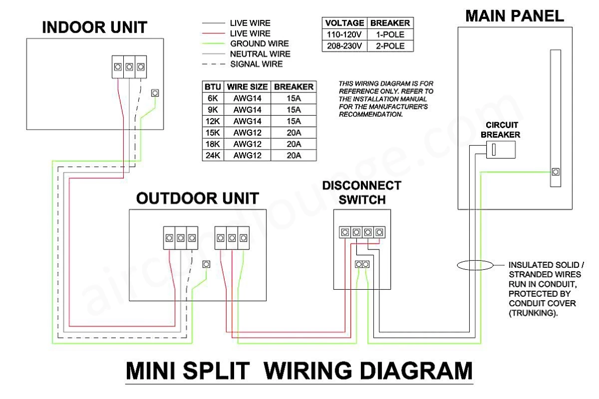
The above wiring diagram shows the complete wiring work needed for a new mini split (208-230V). For 110-120V, there is a slight difference at the disconnect switch which I explain later in the below section.
In addition, I also included the breaker and wire size requirements. However, final wire sizes and connections are still subject to the manufacturer’s recommendation which can be found in the installation manual of your specific mini split. This wiring diagram is for reference only.
I wrote an article to explain how much amps does a mini split draw. Within the article, I show the manufacturer’s recommended breaker and wire size table. Check it out to confirm if yours are the same.
By the way, if you want to learn more about mini split especially how to design it for your house, consider my Mini Split (eBook). You’ll learn what is Mini Split, how to choose and more importantly, spark more design ideas to improve the energy efficient of your house. But, if you need a second opinion or want someone to help you design, then you can consider my consultation service.
Consultation Service
Ask me for HVAC advice such as brand selection, best model, benefits, features, placement, duct size, grille size, how to design, design check, verification and other HVAC related queries.
Procedures to Wire a Mini Split
The wiring installation of a mini split starts at the main electrical panel and then, the disconnect switch, the outdoor unit and finally, the indoor unit. Following are the steps to wire a mini split:
1. Add a Circuit Breaker at the Main Electrical Panel
Most mini splits require only one power supply to the outdoor unit. The indoor unit then takes power from the outdoor unit. Hence, you only need to add one circuit breaker to the main electrical panel of your house (if you don’t have a spare). Also, do check if you have enough spare power for the new mini split.
If you’re using a 110-120V mini split, you need a single-pole circuit breaker. If you’re using a 208-230V mini split, you need a double-pole circuit breaker that carries two 120V live wires.
Depending on your particular mini split, you may need a 15A or 20A circuit breaker. Check the installation manual to see the manufacturer’s recommended circuit breaker size.
For example, an 18000 BTU mini split requires a maximum fuse size of 20A (as stated in the installation manual). Instead of a fuse, we use a circuit breaker. Hence, the circuit breaker size for this mini split is 20A.
It is important to use a good-quality circuit breaker to protect your mini split. Below are my recommended circuit breakers:
- 15A Single Pole: https://amzn.to/3qPvzmd
- 15A Double Pole: https://amzn.to/3CFN4bo
- 20A Double Pole: https://amzn.to/3pcDjyc
A single-pole circuit breaker connects one(1) live wire, one(1) neutral wire and one(1) ground wire. Meanwhile, a double-pole circuit breaker connects two(2) live wires and one(1) ground wire.
Live wires are typically black or red in color while ground wires are typically green in color or just bare copper. Neutral wires are typically in white color. Nevertheless, wire colors vary based on location. So, make sure you identify and mark them carefully.
Typically, the wire size for 6k, 9k and 12k BTU mini splits is AWG14. The wire size for 15k, 18k and 24k BTU mini splits is AWG12. Refer to the installation manual for the recommended wire size. The wire should be sized based on the circuit breaker size.
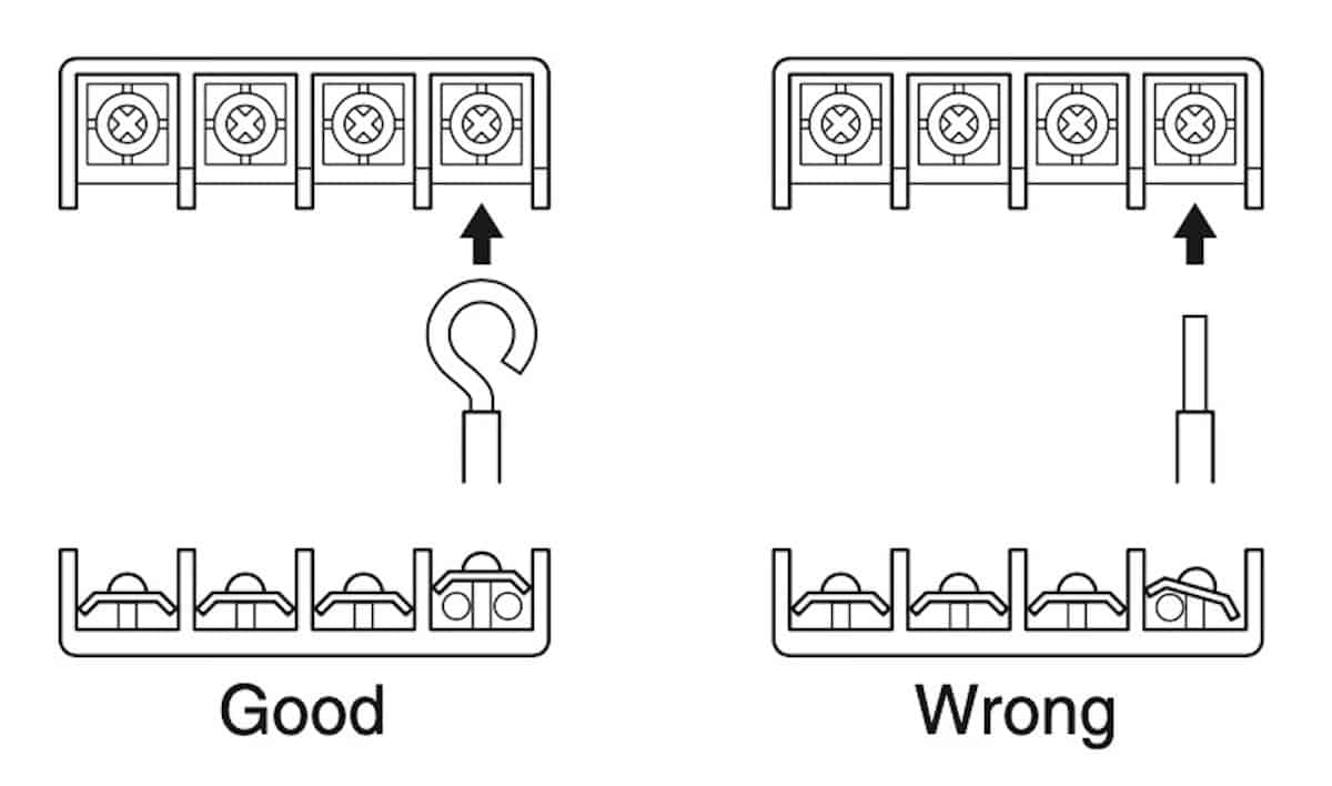
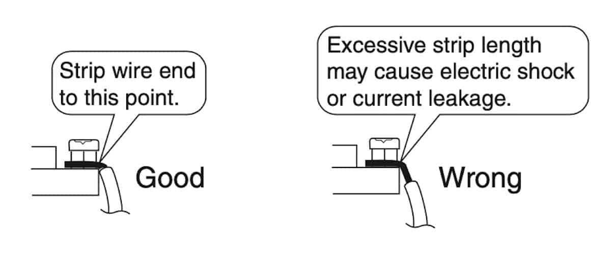
Insulated solid or stranded wires can be used for mini splits. If solid wires are used, be sure to perform curling for better connections. If stranded wires are used, it is recommended to put a round crimp connector at each wire for better connection as well. Also, do not expose the bare wire excessively.
Below illustrates some of the good electrical practices:
As you run the wires from the main panel to the outdoor unit, use liquid tight, non-metallic conduit to protect the wires from rains and sunlight.
Be sure to connect the right type of wires to your mini split. Here are my recommended wires, conduit and connectors:
- Stranded AWG14, 3 Conductor Wires: https://amzn.to/3Jov21a
- Stranded AWG12, 3 Conductor Wires: https://amzn.to/3NECM1j
- Liquid Tight, Non-Metallic Conduit: https://amzn.to/3qTa3x3
- Round Crimp Connectors: https://amzn.to/448rF6u
Once you added the circuit breaker at the main electrical panel and connected the wires to the circuit breaker, pull the other end of the wires to the disconnect switch and proceed to the next step.
2. Install a Disconnect Switch Near the Outdoor Unit
According to the National Electric Code (NEC, latest 2020 edition) article 440.14, if the branch-circuit breaker or switch which is to provide disconnect means is located in a panel that is out of sight (or more than 50 ft [15.0 m] away) from the unit conditioner, another breaker or switch must be provided at the equipment. If the panel breaker or switch does not satisfy the rule here, a separate disconnect means would have to be added in sight from the conditioner.
So, a disconnect switch is needed for your mini split.
Since you need to install a disconnect switch, you need to decide where to put the outdoor unit first. I wrote an article about where to put a mini split indoor and outdoor unit. I recommend you read it so that you don’t miss out anything important.
After you’ve decided the location, mount the disconnect switch on the wall near the outdoor unit.
The disconnect switch should be weatherproof. In addition, sealant should be applied around the switch (if necessary) to prevent water from trapping behind the switch, especially if your wall is uneven.
A fuse is not needed in the disconnect switch because a fuse is already included inside the outdoor unit (on the main control board) to protect the compressor. Thus, any disconnect switch sizes equal or greater than the circuit breaker size can be used.
A disconnect switch typically has four(4) live wire terminals and two(2) ground wire terminals. Follow the disconnect switch wiring diagram to connect the incoming wires from the circuit breaker.
Use a good-quality disconnect switch to ensure good wiring connections. I would recommended this disconnect switch (click to view on Amazon).
For a double-pole circuit breaker (208-230V), the two(2) live wires and the one(1) ground wire should be connected to the respective wire terminals inside the disconnect switch.
For a single-pole circuit breaker (110-120V), the one(1) live wire and one(1) ground wire should be connected to the respective wire terminals inside the disconnect switch. The neutral wire should be taped off (not connecting to any terminal).
Then, place the mini split outdoor unit and proceed to the next step.
3. Connect the Wire Between the Indoor & Outdoor Unit
Prepare a second set of live and ground wires for the connection between the disconnect switch and the mini split outdoor unit. Follow the instruction to connect the live and ground wires at the respective wire terminals inside the outdoor unit.
Prepare a third set of wires consisting one(1) live wire, one(1) neutral wire and one(1) ground wire alongside the one signal wire (communication) that came with the mini split for the connection between the indoor unit and the outdoor unit.
Because the indoor unit requires only a little power, you can use AWG14 for the wire connection from the outdoor unit to the indoor unit even though the outdoor unit is using AWG12. Do not go smaller than AWG14.
Take care to ensure that all wiring between indoor unit and outdoor unit has a consistent connection. Any splices can cause communication errors.
Inside the outdoor unit, follow the instruction to connect the wires at the respective terminals that are meant for the indoor unit. At the other end, terminate the wires at the respective terminals inside the indoor unit including the signal and ground wires.
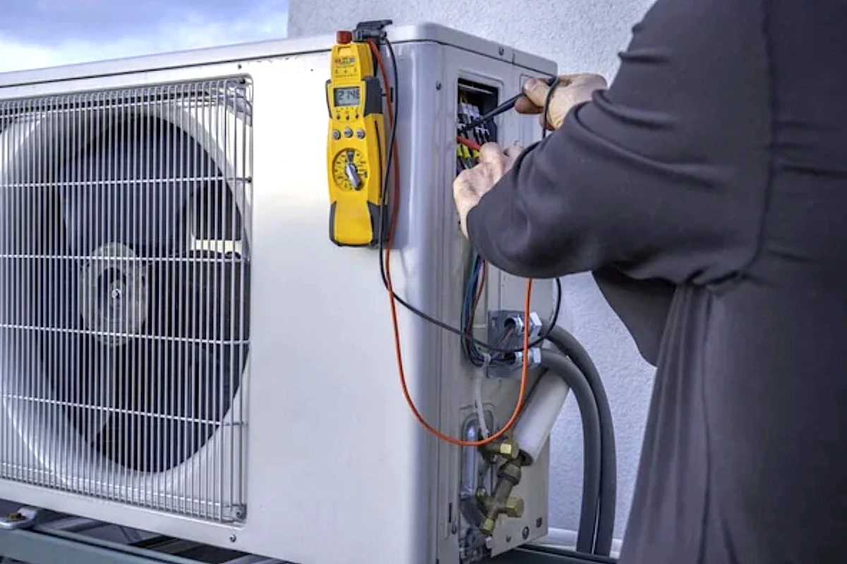
Make sure all wire connections are tight. Use a multimeter to measure the voltage. It should be within the voltage range required by your mini split.
For instance, 208-230V ± 10% = 187-253V.
If the voltage is out of range, electronics in the mini split may be damaged. Also, check the voltage variation between phases, it should not be more than 2%.
If you don’t have a multimeter yet, I suggest you get one with a clamp (click to view on Amazon) so that you can measure the running amp which is essential for air conditioning work.
After everything is checked, turn on the mini split and monitor for any abnormalities.
Wiring a Mini Split Thermostat
Mini splits by default are controlled by remote controllers. However, you can choose to use the optional wired controller or thermostat. Here are the steps to wire the thermostat of a mini split:
- Mount the wired controller near the indoor unit.
- Connect the remote controller cord to the remote control adapter.
- Pull the five-wire cord from the adapter to the indoor unit and connect it to the respective terminal.
The remote controller cord may not be supplied alongside the wired controller. So, be sure to check and prepare one before the installation.
Wiring a Mini Split Condensate Pump
Mini splits usually don’t provide a specific wire terminal for a condensate pump. To wire a mini split condensate pump, refer to the wiring diagram of your specific condensate pump.
Condensate pumps can take power from a separate source or loop from the indoor unit. Some condensate pumps provide you instructions to intersect the signal wire of the mini split so that when the condensate pump fails, it stops the operation of the mini split to prevent overflow.
Depending on where you put your mini split, you may or may not need a condensate pump. I wrote an article to explain when do you need a condensate pump for your mini split. I recommend you read it if you think you might need one.
Mini Split Signal Wire (Communication)
The indoor and outdoor unit of a mini split communicates through a signal wire that is often provided when you purchase a mini split. However, you also can use a standard insulated AWG16 as a replacement for the signal wire (DC 12/24V).
If your mini split has a communication error, try keeping the signal wire away from any high-power wires. This will eliminate the electrical interference on the signal wire. Alternatively, use a highly-screened wire to reduce the interference. This type of wire is also known as a screen/shield wire.
FAQs about Wiring a Mini Split
- Can You Use a 60A Disconnect Switch on a 20A Circuit?
Yes, you can use a 60A disconnect switch on a 20A circuit. The 60A is referring to the current-carrying capacity of the wire terminals of the disconnect switch. If the circuit is only 20A, a 60A disconnect switch is safe. However, if there is a fuse in the 60A disconnect switch, a 20A circuit will most likely bypass the 60A fuse, rendering the fuse useless. - Are Stranded Wires Better for Mini Splits?
Yes, stranded wires are preferred over solid wires because stranded wires have better contact surface at the wire terminals. However, if curling is performed, solid wires are as good as stranded wires. - How Many Amps Does a Mini Split Disconnect Switch Use?
A mini split disconnect switch requires to be at least 15A. If the mini split requires 20A, the disconnect switch must also be rated at 20A. Using a disconnect switch with a greater amp than the mini split is fine.
Lastly, consider my Mini Split (eBook) if you want to know how can you use Mini Split in your house. If you still have doubt or not feeling confident enough, feel free to consult me.
Consultation Service
Ask me for HVAC advice such as brand selection, best model, benefits, features, placement, duct size, grille size, how to design, design check, verification and other HVAC related queries.


