5 Types of HVAC Controls (Thermostat, DDC, 0-10V & Dry Contact)
HVAC equipment such as air conditioners, ventilation fans, chillers, cooling towers and pumps need to receive signals in order to run, stop, regulate and trip. Without signals, these machines don’t know what to do.
The signals to HVAC equipment are triggered by devices such as temperature sensors, starters and relays, and they are transmitted through communication cables such as CAT5 cables and PVC cables.
There are a few different types of signals that can be transmitted through the communication cables. Some of them are commonly known as dry contact, 0-10V and 4-20mA. Different types of signals have different characteristics. For instance, 0-10V signal is more common but subjected to voltage drop and thus, weak signal or inaccurate signal.
As an HVAC engineer, you’ll be dealing with these controls, signals and terms very often especially when you are handling projects involving smoke spill systems, pressurization systems, chilled water systems and variable air volume boxes.
Many people explain HVAC controls in a way that is extremely difficult for HVAC engineers to understand. All the programming languages, protocols and computer terms used in their explanation are not really used and practiced by HVAC engineers most of the time.
So, I’ll explain HVAC controls with common terms that you’ll find used by the people working in the HVAC industry. Let’s get started.
Types of HVAC Controls
We can view HVAC controls as three parts; a) operation control, b) temperature control and c) air quality control. I don’t think anyone had broken down HVAC controls as I do but I find it is better for people to understand.
Operation control involved the start and stop of HVAC equipment such as air conditioners and ventilation fans. Besides, it also includes variable speed control. In other words, it tells the equipment to run, stop or run at what percentage of speed.
After operation control is temperature control. Once an air conditioner started to run, it needs to know how much power should it be running and how much cooling power should it be giving. Usually, a thermostat or temperature sensor is needed to support the control.
Air quality control is often associated with carbon dioxide and carbon monoxide control. To maintain good indoor air quality, carbon dioxide level must be monitored and controlled. If the carbon dioxide level is too high, ventilation fans must run to dilute indoor air with outdoor air.
Now, let’s take a few common HVAC equipment and dive deeper into their control system starting with the equipment itself all the way to the triggering point.
1. Thermostat Control
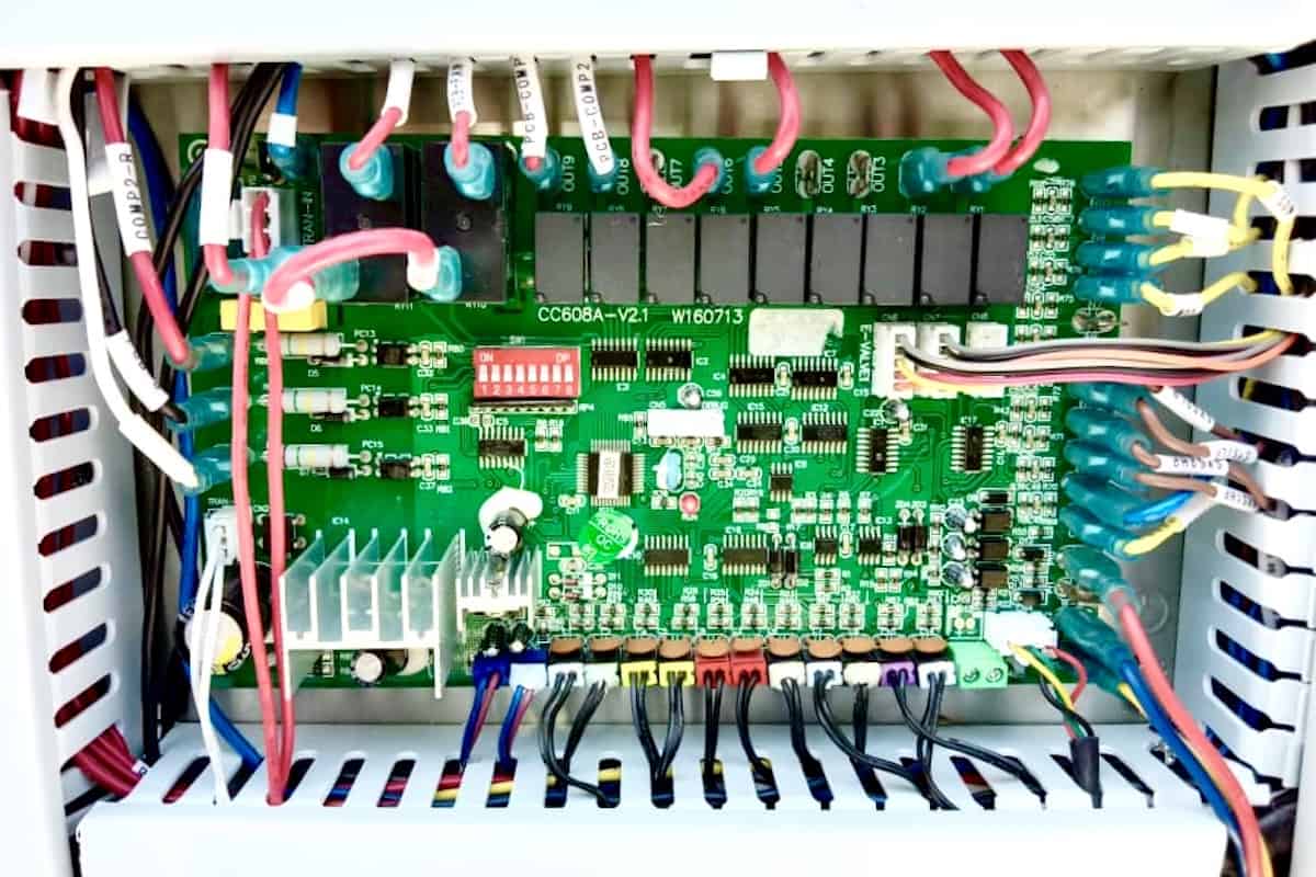
A mechanical room can be equipped with electrical transformers and fire pumps. Equipment such as transformers generates a substantial amount of heat during operation. So, a ventilation fan is needed to control the temperature inside the mechanical room to prevent the transformers from overheating.
The purpose of the ventilation fan is to exchange the air inside the mechanical room with outdoor air so that the temperature inside the room equals the temperature of outdoor air. So, the triggering point for the ventilation fan is high temperature.
Let’s say the temperature inside the mechanical room can’t raise above 30ºC (86ºF). So, the ventilation fan must operate when it detects the room temperature exceeding 30ºC (86ºF). But, how does it detect?
Thus, a thermostat is needed to control the operation of the ventilation fan.
A thermostat is a temperature detecting device that allows users to set the desired temperature setpoint. When the room temperature hits the temperature setpoint, the thermostat will close an electrical circuit thereby providing a signal to the control panel of the ventilation fan to provide power to run the ventilation fan.
But, where does the electrical circuit comes from?
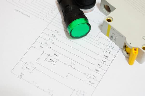
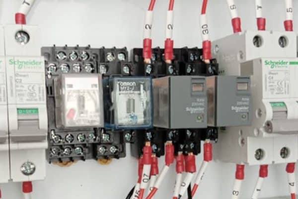
The ventilation fan must have a power supply to run and the power supply is coming from a control panel. The control panel has a direct-online starter that requires a 230V signal to activate thereby closing the contact and providing power to the ventilation fan.
Usually, the control panel had its wiring done such that the neutral line is always connected to the direct-online starter and the live line is pulled all the way to the thermostat and back to the control panel. So, the thermostat acts as a gateway for the starter to activate.
Now back to earlier, the mechanical room gets hot enough to trigger the thermostat. Next, the thermostat closed its contact and the 230V electrical circuit is completed which allows the direct-online starter to activate thereby providing power to operate the ventilation fan. Once the temperature is reduced back to normal, the thermostat release the closed contact and the power supply to the ventilation fan is cut off.
In short, every piece of HVAC equipment has a trigger point. They are always in standby mode, waiting for a device to trigger and give a signal for them to operate in different manners.
The above example can be considered as the most basic form of HVAC control. Now, let’s take a look at a more complicated control system.
In the meantime, I would like to inform you that you can learn quicker by getting my HVAC Begin (eBook) if you’re a beginner. But, if you have a year or two of experience, then I would suggest you consider my HVAC Basics (eBook). Nonetheless, I encourage you enroll in my HVAC Beginner Course: 10 Days to Become Competent in HVAC if you want to equipped yourself with a complete set of basic HVAC skills.
HVAC Beginner Course
Learn the most basics and foundational HVAC skills including cooling capacity calculation, equipment selection, duct sizing, pipe sizing, exhaust fan sizing, controls, electrical and more.
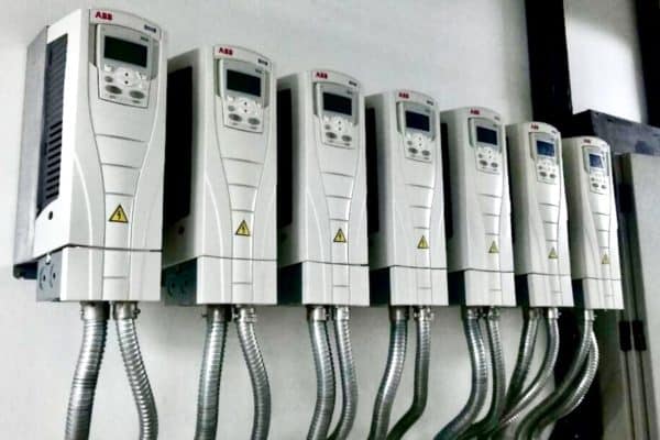
2. 0-10V Signals
Variable air volume or VAV box is an airflow device that controls and distributes air based on room temperature. VAV boxes are usually found in HVAC systems that involved air handling units (AHUs).
VAV boxes are installed in between supply air ducts and they have a mechanism to open or close so that they can control the amount of air flowing through them thereby controlling the amount of air supplied to a room. By controlling the supply airflow, the room temperature can be controlled and maintained.
In order for a VAV box to know how much air can be allowed to pass through, it must be able to measure the airflow first. So, a mini pitot tube is commonly found in VAV boxes to measure airflow.
Next, the VAV box must know the relationship between airflow and temperature. In other words, it must know how the amount of supply air affects the room temperature. Hence, an algorithm or program must be written by people and built within the VAV box.
Again, to know the room temperature, a thermostat is needed. But this time, the thermostat is more advance. It needs to give a range of signals instead of the basic close and open contact because the VAV box will open at a percentage according to the room temperature. As the name suggests, it is a VARIABLE air volume box.
Examples of a range of signals are 0-10V and 4-20mA. These kinds of signals can be used for variable speed control. For instance, 0V equals 0 cfm, 1V equals 50 cfm, hence, 5V equals 250 cfm and 10V equals 500 cfm which is fully opened already.
If the room temperature is set at 25ºC, the signal can be +0.2ºC equals 1V, hence, +1ºC equals 5V and +2ºC equals 10V. So, if the room temperature increases from 25ºC to 26ºC, a 5V signal will be sent from the thermostat to the VAV box thereby providing 250 cfm of airflow to the room.
However, all HVAC control devices must be calibrated in order to deliver precise results. For instance, if the same thermostat is inaccurate, it may give a 10V signal when the room temperature is only increased by 1ºC. Thus, the VAV box will supply 500 cfm of airflow to the room which may cause overcooling problems.
So, appropriate and regular calibration of control devices is extremely important in HVAC controls. Otherwise, an excellent high-energy-efficiency HVAC design means nothing after a few years when all the control devices are not accurate anymore.
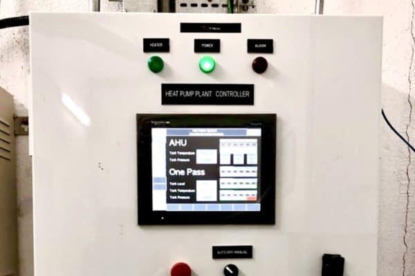
3. DDC & PLC Control
Carbon dioxide (CO2) sensors and carbon monoxide (CO) sensors are commonly used in HVAC systems. CO2 sensors are mostly used to make sure the people living in the building have sufficient oxygen and the CO2 level is not dangerous.
On the other hand, carbon monoxide (CO) sensors can be found in underground basement carpark floors. They are used to detect the level of CO that is emitted by cars’ exhaust. If the CO level is too high, ventilation fans will operate to replace the basement air with fresh outdoor air.
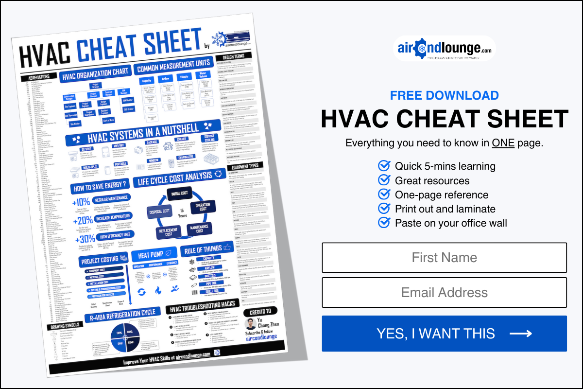
CO2 and CO sensors often use DDCs or direct digital controllers to communicate with the associated ventilation fans. Because these sensors are not as simple as a few data points, they require to communicate using a protocol such as BACnet or Modbus.
A typical residential building can have 3 floors of basement carpark. Depending on the floor area, the total number of CO sensors can be around 40 units. Usually, a DDC can only connect up to around 10-12 CO sensors depending on the specification. So, the system may have 4 DDCs.
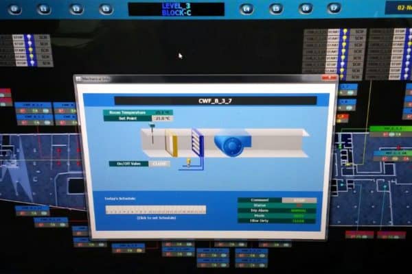
The function of DDCs is to collect all the data points from all the CO sensors. Then, all DDCs are connected to one network device where it is sort of like a central processing device. Engineers and programmers install a program into the network device to control the behavior of the ventilation fans based on the signals coming from the CO sensors.
Because there may be 4-5 CO sensors controlling one ventilation fan, a computer program is needed to form a logic on how to operate the ventilation fan or how fast the ventilation fan have to run.
In a more complex control system, a PLC or programmable language controller may be required to perform multiple tasks based on multiple inputs from multiple sensors, valves and other control devices.
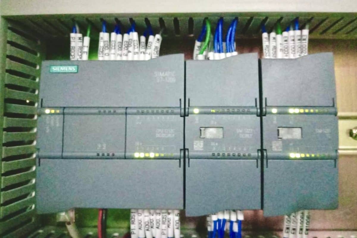
With a program, we can tune and fine-tune the result as desired. The fine-tuning work is generally not restricted by hardware. As long as we have sufficient hardware to cater to the data points, we only need to play around with the software to get the perfect result.
The program may look something like “if CO sensor A = 45ppm, ventilation fan A = run”. I’m not a programming expert so pardon me if it looks too simple. Nevertheless, it is basically what I learned from my HVAC projects.
With the above three examples, you have the basic concept of HVAC controls. If you encounter a more complicated system, just break them down as small as you can and apply the concept. You’ll find it is all controlling the same way.
4. Dry Contact
Almost all HVAC equipment has dry contact signals. There are dry contact and wet contact signals. Dry contact means there is no electrical current flowing through the cable. It is just a simple contact.
Most of the time, you’ll find a dry contact signal in air conditioners’ signal feedback and fire relays. In commercial buildings, there may be thousands of air conditioning units. Hence, the building control room must be able to see the operation status of all air conditioners.
So, air conditioners will give a “run signal” whenever they are triggered to run and the signal is often in the form of a dry contact. Relays are served to receive the dry contact signal and many other types of signals such as 12Vdc and 24Vdc.
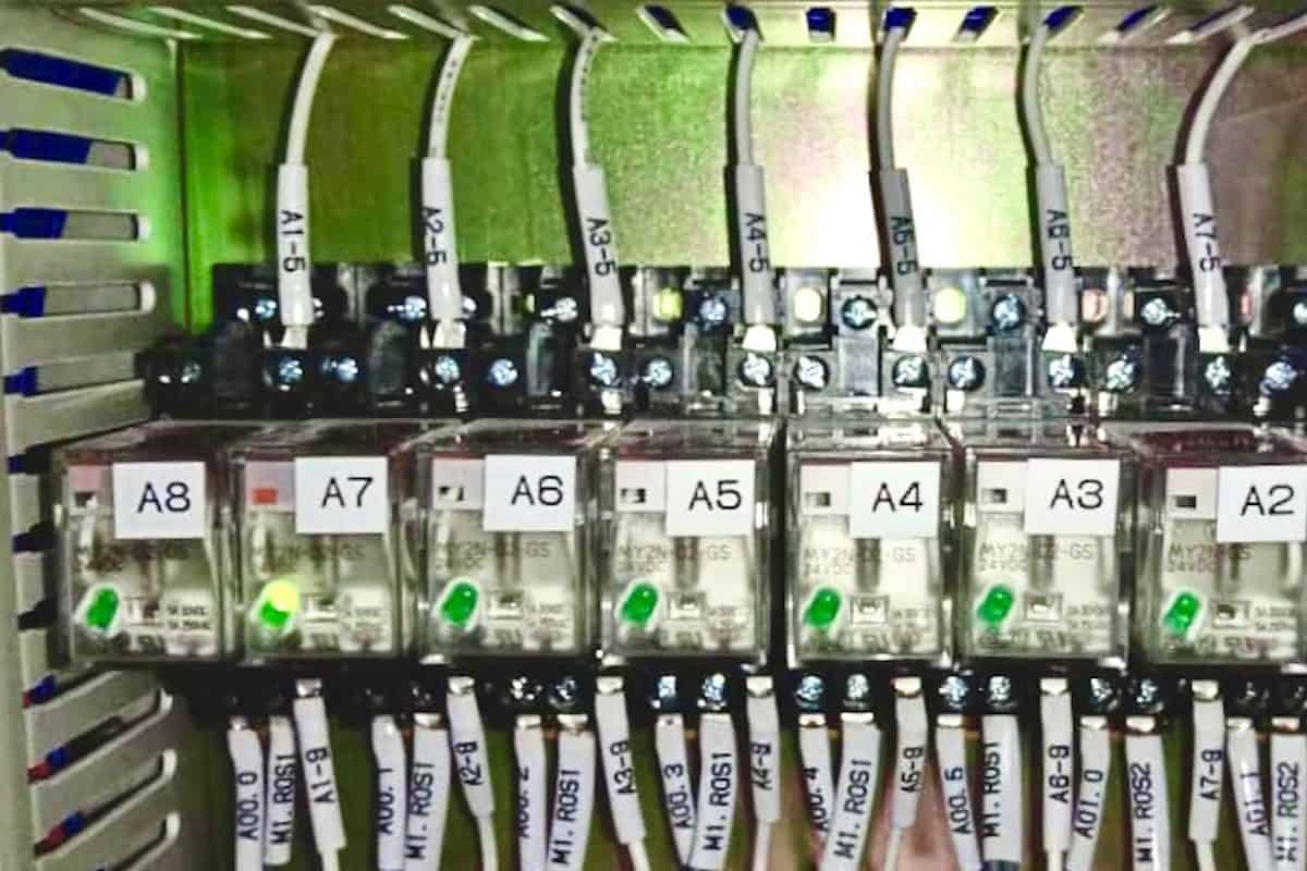
Inside the control panel of the air conditioners is a small transformer that converts 240Vac to 24Vdc. Then, the control panel supplies the 24Vdc to the air conditioners and back to its relays. Finally, the building control system taps the control panel to read the signal from the relays.
When the air conditioners are triggered to run, they closed the “run status” contact thereby allowing the 24Vdc to pass through and energize the relays and thus, giving a “run signal” to the control room. Such a signal is called dry contact for the air conditioners, meaning they don’t give any power but only closed the contact.
On the other hand, wet contact signals involved supplying power like 24Vdc directly to energize a relay thereby providing signals. Usually, devices that involved an electronic board prefer to use dry contact signals because sending and receiving power directly has a risk of burning the electronic board.
Dry contact signals are also commonly found in fire signals. During a fire, the building’s fire protection system will send dry contact signals to all HVAC equipment in order to trip and stop their operation to prevent the spread of smoke.
5. BACnet and Modbus
BACnet and Modbus are both protocols or “languages” for HVAC equipment to communicate. BACnet or building automation control network is developed by ASHRAE and it is sort of a universal language. Most HVAC equipment are equipped with BACnet with some HVAC equipment are still using Modbus.
Modbus can be viewed as a “private language”. HVAC equipment manufacturers will have their own protocol which is often written in Modbus. Good or reputable manufacturers will have both BACnet and Modbus or build their products solely based on BACnet protocol so that their machines can talk to other machines.
If a Modbus machine wants to communicate with a BACnet machine, a converter or a “language translator” device can be used. Otherwise, the Modbus code must be provided to the BACnet programmer for him/her to manually translate (see what input results in what output).
Lastly, consider my HVAC Begin (eBook) if you’re a beginner and you want to have a foundational knowledge in HVAC. But, if you have a year or two of experience, then I would suggest you consider my HVAC Basics (eBook). Nonetheless, I encourage you enroll in my HVAC Beginner Course: 10 Days to Become Competent in HVAC if you want to equipped yourself with a complete set of basic HVAC skills.
HVAC Beginner Course
Learn the most basics and foundational HVAC skills including cooling capacity calculation, equipment selection, duct sizing, pipe sizing, exhaust fan sizing, controls, electrical and more.
If you have anything to add (or ask) about this topic, leave a comment down below!