How HVAC Relays Work? (Actual Applications)
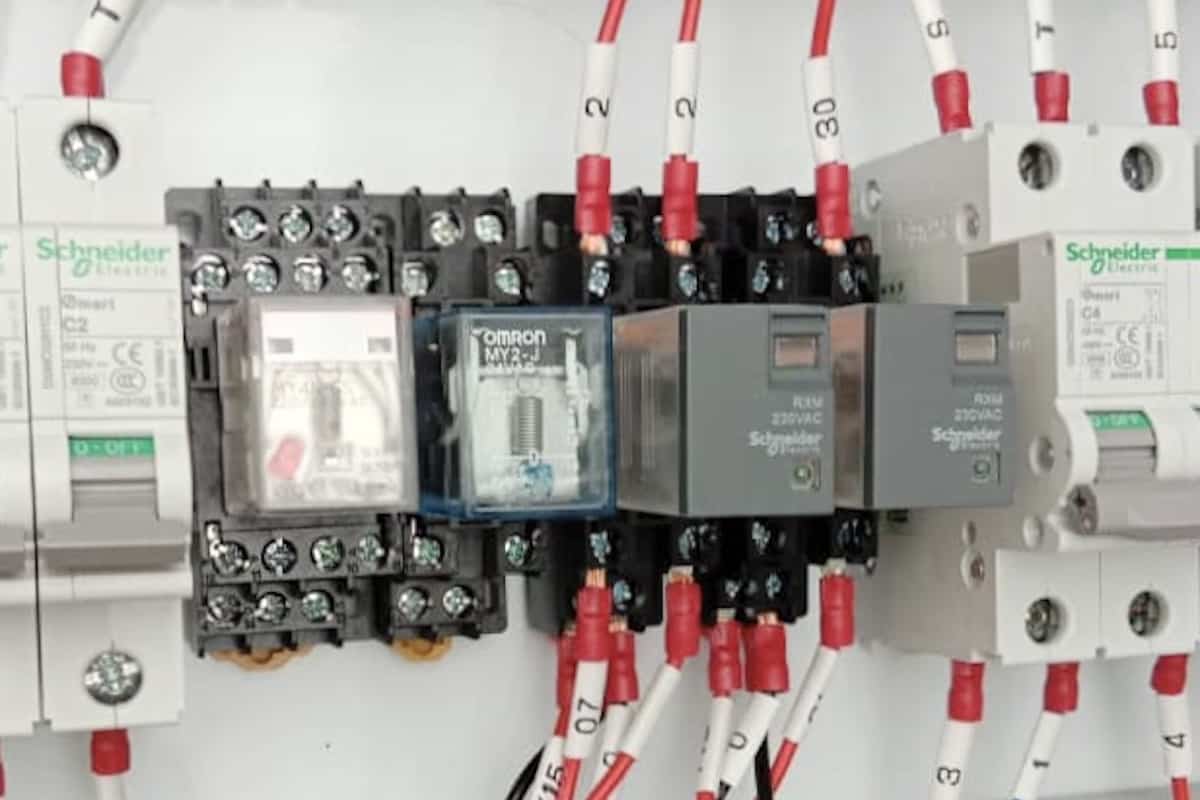
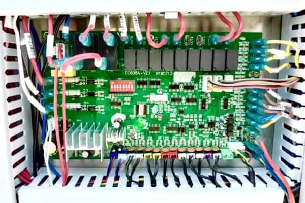
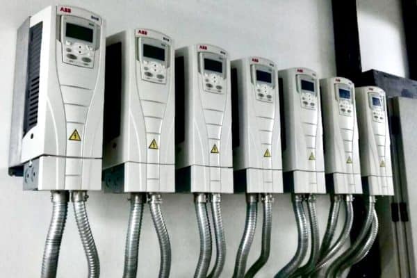
Relays can be found in almost all HVAC systems. They are typically located inside HVAC control panels or within the HVAC unit itself. I’ve always been curious how HVAC relays work. So, I did some research.
It turns out that HVAC relays usually use either 24Vdc or 240Vac signals. When an HVAC relay receives a signal, the magnetic coil within the relay gets energized, causing the open contact relay to close its contact thereby allowing electrical current to flow through for control purposes.
Many people are having a hard time understanding how HVAC relays work. Using simple terms and diagrams, I’ll explain how they work and how you can check if your relays are good.
How HVAC Relays Work?
There are only handful of types of relays used in HVAC. While they may seem different, but they are actually working the same way. It is just that they are using different signals.
Many relays use a 24Vdc signal. 24Vdc stands for twenty-four-volt direct current. As the name suggests, this type of relay required a 24V direct current to activate.
In HVAC, 24Vdc relays can be found in the control panel of almost all equipment including air handling units, smoke extraction fans, pressurization fans, kitchen exhaust fans and toilet exhaust fans. They are typically used for the fire signal. Hence, they are also known as fire relays.
Fire Relays
Fire relays are common and essential in HVAC. During a fire, the building’s fire protection system will send a fire signal to all HVAC control panels thereby energizing the respective fire relay and tripping the respective equipment.
Unrelated fans must not be in operation during a fire to prevent the spread of fire smoke.
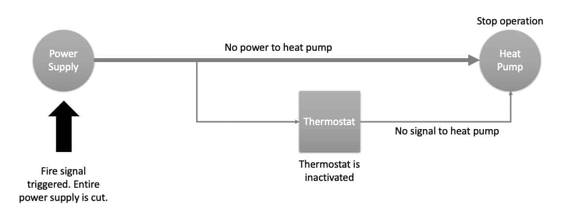
The following is an example of the configuration of a typical fire relay used in a heat pump system:
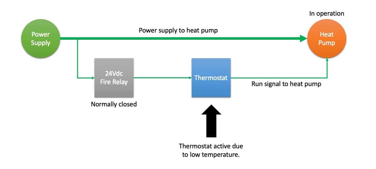
From the above diagram, the control panel supplies power to the heat pump. However, the heat pump operation is depending on the signal from the thermostat. Under normal circumstances, the 24Vdc fire relay is not activated. It is in a closed position to allow the electric current to pass through for controls.
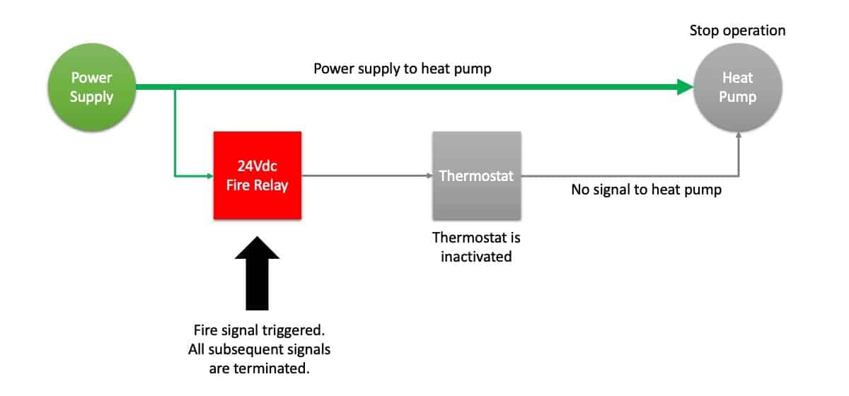
During a fire, the building’s fire protection system sends a 24Vdc power/signal to energize the 24Vdc fire relay. Upon receiving the 24Vdc power/signal, the magnetic coil within the relay energized and switch from a closed position to an open position.
HVAC relays have two positions; a) normally closed and b) normally open.
In the case of the above fire relay, it is a normally closed type. So, when a fire signal is received, its internal mechanism is flipped from closed to an open position, stopping all subsequent signals.
Therefore, the thermostat is inactivated thereby inactivating the heat pump.
Such a tripping method is also known as “tripping the control” and it is preferred over using a shunt trip breaker. A shunt trip breaker has a magnetic coil similar to relays. Instead of giving a fire signal to a relay, the fire signal goes directly to the shunt trip breaker thereby cutting the entire power line.
Shunt trip breakers are a more simple approach to handling fire signals. However, they are not suitable for HVAC units that have compressors because most of the time, compressors required a buffer time before they stop running completely. Cutting off the power suddenly may cause harm to the compressors.
In the meantime, I would like to inform you that you can learn quicker by getting my HVAC Begin (eBook) if you’re a beginner. But, if you have a year or two of experience, then I would suggest you consider my HVAC Basics (eBook). Nonetheless, I encourage you enroll in my HVAC Beginner Course: 10 Days to Become Competent in HVAC if you want to equipped yourself with a complete set of basic HVAC skills.
HVAC Beginner Course
Learn the most basics and foundational HVAC skills including cooling capacity calculation, equipment selection, duct sizing, pipe sizing, exhaust fan sizing, controls, electrical and more.
Status Feedback Relays
Status feedback relays are the second most seen relays in HVAC. Typically, status feedback relays use a 240Vac signal. However, other signals such as 24Vdc and 24Vac are also quite common. It is really depending on HVAC manufacturers.
Similar to 24Vdc, 240Vac stands for two-four-zero-volt alternating current. Again, this relay requires 240V alternating current to activate its magnetic coil.
Status feedback relays are used to receive various statuses of an HVAC unit. Some of the examples of statuses are on/off status or start/stop status and trip alarm.
The following example continues the heat pump system but included a new on signal feedback as well as the relay:
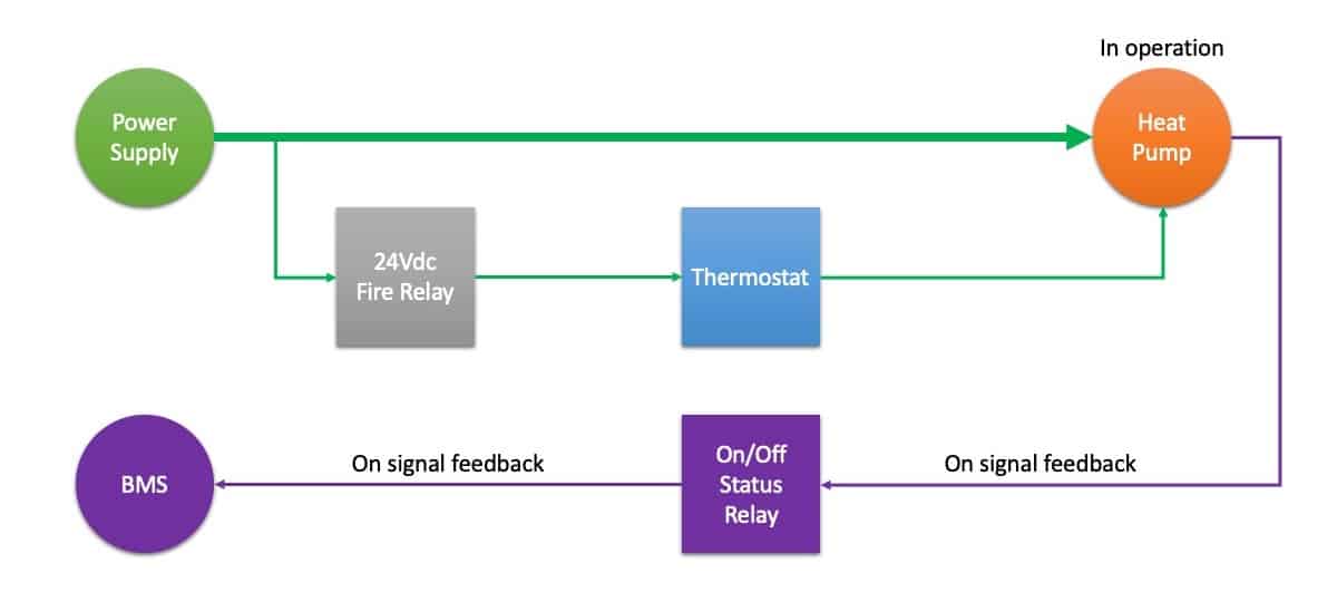
Upon the heat pump operates, it sends an on-signal in the form of 240Vac or 24Vac or others to energize the respective relay thereby informing the building management system (BMS) or control room about the status of the heat pump operation.
Command Relays
In HVAC, relays also can work the opposite way. A selector switch can be placed before the thermostat to overwrite from thermostat control to BMS control (better known as from auto mode to BMS mode).
However, the selector switch is physically placed on the control panel, not near the thermostat of the heat pump.
When the selector switch is turned to BMS mode, the thermostat is no longer controlling the heat pump. Instead, the heat pump requires a signal from the BMS to run.
The following example continues to show the BMS run signal to the heat pump:
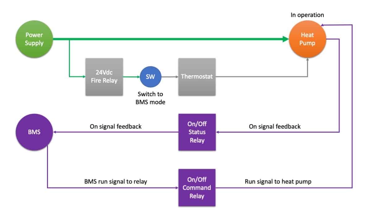
So, relays used in HVAC can be used for tripping, status feedback, start/stop control and a few other purposes.
How to Test a Relay?
After knowing the basic operation of relays, we can test a relay separately without relying on the signal source. For instance, we can use a car battery, which is a 12Vdc battery, to energize a 12Vdc relay and thus, starting an HVAC unit.
Typically, relays will lid green color light if they are successfully energized. However, some relays do lid red color when they are activated. If a relay does not lid, it is probably broken.
Other than that, if your HVAC unit is not running and you are suspecting it is the relay that is causing the problem, you can simply use a 1.5mm2 PVC cable to bypass the relay and see if your HVAC unit will run. After all, the relay only acts as a switch.
4-Pin, 8-Pin and 11-Pin Relay
The pin represents the “leg” of the relay. 8-pin relays have 8 “legs” and they are capable of controlling two devices using only one signal.
Below is the wiring diagram of a typical 8-pin relay:
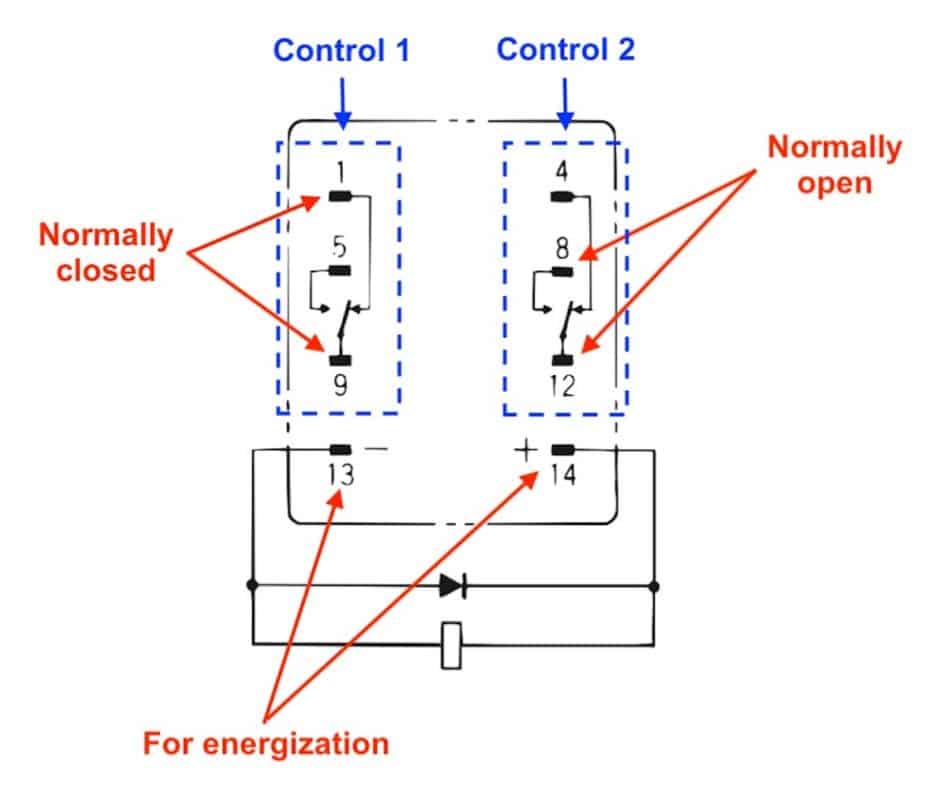
Terminal 13 and 14 is where you need to connect to the signal source. It can be directly to the HVAC unit or a power supply or converter or transformer.
For the output or the device you wish to control, connect terminal 1 and 9 for normally closed operation and connect terminal 5 and 9 for normally open operation. The same thing applies to the second control.
So, if you have a 11-pin relay, you can control or provide signals to 3 devices with one signal as well as if you have a 14-pin relay, you can control 4 devices simultaneously.
Lastly, consider my HVAC Begin (eBook) if you’re a beginner and you want to have a foundational knowledge in HVAC. But, if you have a year or two of experience, then I would suggest you consider my HVAC Basics (eBook). Nonetheless, I encourage you enroll in my HVAC Beginner Course: 10 Days to Become Competent in HVAC if you want to equipped yourself with a complete set of basic HVAC skills.
HVAC Beginner Course
Learn the most basics and foundational HVAC skills including cooling capacity calculation, equipment selection, duct sizing, pipe sizing, exhaust fan sizing, controls, electrical and more.
If you have anything to add (or ask) about this topic, leave a comment down below!


