How to Read HVAC Duct Drawings?
Duct drawings are HVAC drawings that shows the layout of ducted air conditioning systems and mechanical ventilation systems. They are very important for HVAC engineers. So, how do you read HVAC duct drawings?
To read HVAC duct drawings, start by identifying the HVAC equipment location and details. Then, look at the connected ducts and their duct sizes as well as the corresponding duct fittings. Afterward, determine the type of grilles and grille quantity associated with the ductwork and finally, check the airflow direction of the duct system.
Beginners may find it difficult to understand the terms, symbols and icons used in HVAC duct drawings. Hence, I’ll break this post into two parts; a) air conditioning systems and b) mechanical ventilation systems. Then, I’ll explain them section-by-section for easy understanding.
Air Conditioning Systems
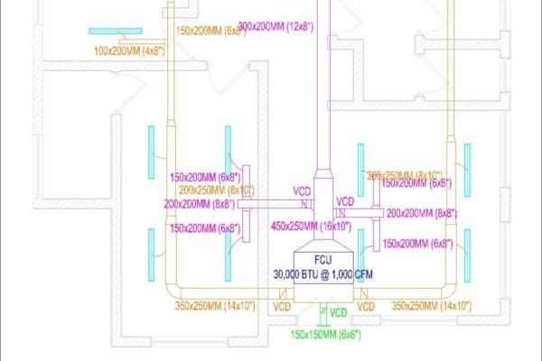
Before we jump into it, below is a typical ducted air conditioning layout drawing. I’ll be zooming in to different sections for the explanation. This is for you to follow along easier if you also have the same drawing.
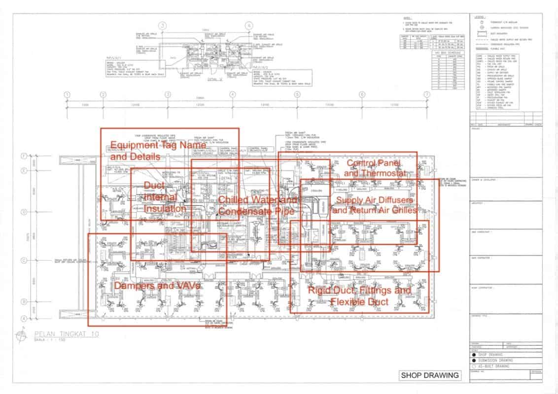
Equipment Tag Name and Details
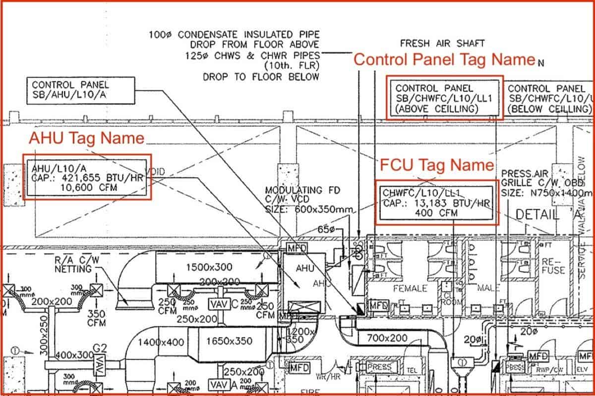
Similar to ventilation fans, air conditioning units also have a tag name and a few details written on shop drawings. Details included in the drawing are as follow:
Tag name > Brand > Model > Cooling Capacity > Airflow > Static Pressure > Weight
However, if the drawing is too congested, some of the details may be excluded. In the above drawing, the most important tag name, capacity and airflow are included only.
The tag name follows the same principle covered in the previous course about the ventilation system. Every major piece of equipment should have a tag name including control panels.
AHU stands for air handling unit while FCU stands for fan coil unit. If CHW is added before AHU/FCU, the whole thing stands for chilled water fan coil unit.
Common acronyms used for air conditioners are as follow:
| Acronym | Description |
|---|---|
| AHU | Air Handling Unit |
| FCU | Fan Coil Unit |
| CHW | Chilled Water |
| CW | Condenser Water |
| IDU | Indoor Unit |
| ODU | Outdoor Unit |
| CHWP | Chilled Water Pump |
| CWP | Condenser Water Pump |
| VRV | Variable Refrigerant Volume |
| VRF | Variable Refrigerant Flow (same as VRV) |
The unit of measurement for cooling capacity is mostly btu/hr or British Thermal Unit per Hour. However, some people prefer to use other units of measurements.
Basically, there are only 4 units of measurements for cooling capacity:
- btu/hr or BTU = British Thermal Unit per Hour
- RT or Ton = Refrigeration Ton (1 RT is 12,000 btu/hr)
- kW = kilo Watt (1 kW is 3,412 btu/hr)
- HP = horsepower (1 HP is ~9000 btu/hr)
Including the equipment dimension and weight is very handy if you have sufficient space in the drawing. Installers need the dimension and weight when handling the logistic and positioning of the equipment.
Notice that the control panel has an additional “above ceiling” indicating that it should be installed above the ceiling rather than below the ceiling. At the same time, it is assumed that you know to put a ceiling manhole under the control panel for service and maintenance.
Rigid Duct, Fittings and Flexible Duct
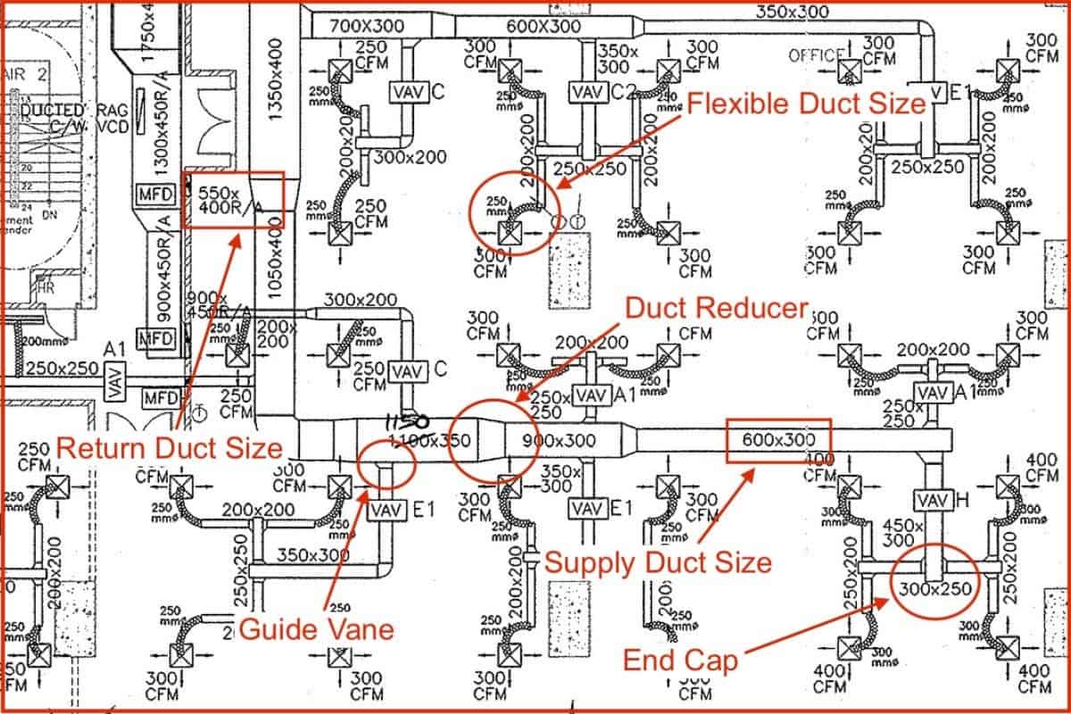
Similarly, the duct size, duct reducer and guide vane are being drawn the same way as the ductwork of the ventilation system. However, there are a few new terms used in the air conditioning system.
Common acronyms used for the air conditioning system:
| Acronym | Description |
|---|---|
| SA | Supply Air |
| RA | Return Air |
| SAD | Supply Air Duct |
| RAD | Return Air Duct |
| FAD | Fresh Air Duct |
Flexible ducts are drawn in the shape shown in the above drawing. If a rigid duct is drawn very close to a grille without a flexible duct, it means that NO flexible duct is used but only rigid ducts.
For the air conditioning duct, the duct sizes indicated are excluding the duct insulation. Hence, if you are determining anything related to how much the duct occupied the space, you need to refer and add the insulation thickness on top of the duct size indicated in the drawing unless otherwise specified.
Supply Air Diffusers and Return Air Grilles
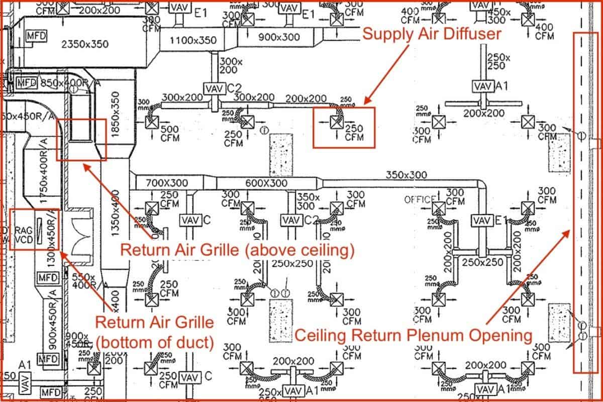
If you look closely, some grilles are attached to a flexible duct while some grilles don’t. Those grilles that have a flexible duct attached are supply air diffusers. Grilles without a flexible duct are return air grilles.
Some of the common acronyms used for grilles are:
- SAG = Supply Air Grille
- SAD = Supply Air Diffuser
- RAG = Return Air Grille
Based on the layout of the supply air diffusers and return air grilles in the above drawing, we know that this system is designed to use the entire ceiling as a return air plenum space for the air handling unit.
Furthermore, there is an entire stretch of ceiling return plenum opening near the exterior wall to allow cold air to return back to the air handling unit, moving through the space above the ceiling. At the same time, the cold air also returns back to the air handling unit via the return air grilles.
In the meantime, I would like to inform you that you can learn quicker by getting my HVAC Begin (eBook) if you’re a beginner. But, if you have a year or two of experience, then I would suggest you consider my HVAC Basics (eBook). Nonetheless, I encourage you enroll in my HVAC Beginner Course: 10 Days to Become Competent in HVAC if you want to equipped yourself with a complete set of basic HVAC skills.
HVAC Beginner Course
Learn the most basics and foundational HVAC skills including cooling capacity calculation, equipment selection, duct sizing, pipe sizing, exhaust fan sizing, controls, electrical and more.
Dampers and VAVs
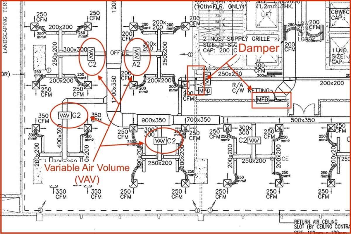
Dampers used for air conditioning system is the same as the ventilation system. Here, we have a VAV or Variable Air Volume which is a box that controls the amount of supply air to a particular space.
Typically, VAVs required straight duct clearance (about 600mm) in the front and back. As you can see in the above drawing, sufficient space is allowed before putting the VAV.
Tags beside the VAV such as C2, G2 and A2 are just a name given to each type of VAV for us to read better and avoid installing the wrong one since VAVs look more or less the same from the outside.
Duct Internal Insulation
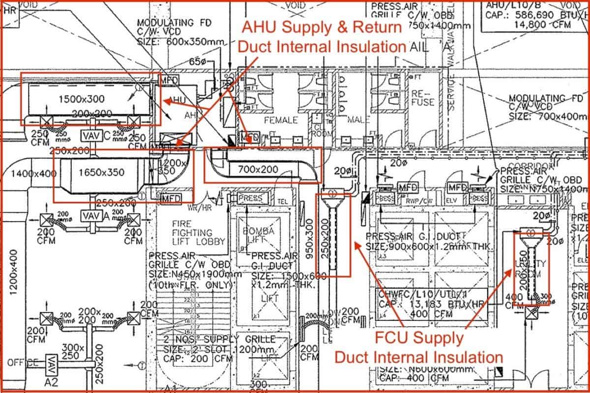
From the above drawing, you can see that there is a dotted line drawn inside air conditioning ducts. The dotted line starts from the air conditioner and covers only a small section of the duct.
These indicate that insulations are needed inside the duct. Duct internal insulation is required to reduce the noise transmitted from air conditioners to the office space through the duct.
Chilled Water and Condensate Pipes
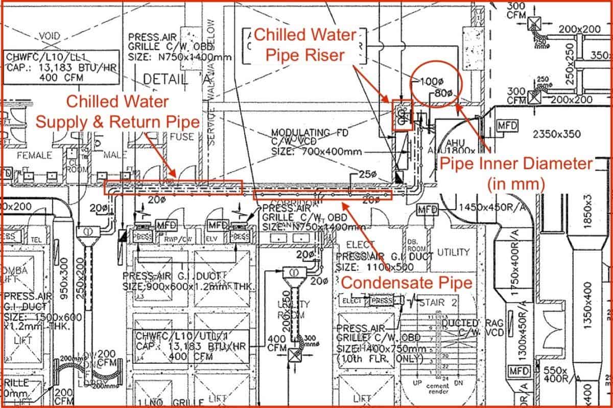
Air conditioning pipes can be drawn in several forms. The most common one is the dotted line as shown in the above drawing. Lines with circles are often used for condensate pipes. Nevertheless, there is no fixed rule and you can always refer back to the legend to confirm.
Control Panel and Thermostat
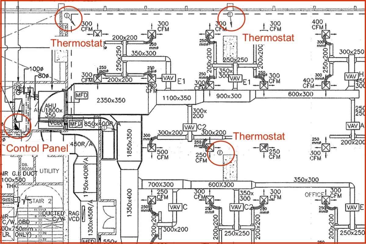
Most control panels are drawn as shown in the above drawing. Some people may not color half of the rectangular but they are generally shaped as a rectangular box with a diagonal line. As for thermostats, they always have the word “T” whether is inside a circle or a square.
In the above drawing, each thermostat corresponds to one VAV. Hence, there are many thermostats shown in the drawing. Typically, there is only one thermostat for one air conditioner.
Ceiling Manholes
I would suggest everyone to include square-shaped ceiling manholes in their shop drawings where necessary. Many times, people miss out on ceiling manholes. Later, they have arguments due to heavy variation orders from the ceiling contractor. Sometimes, the arguments end up with ceiling manholes get voided, causing a lot of problems for future maintenance.
Mechanical Ventilation System
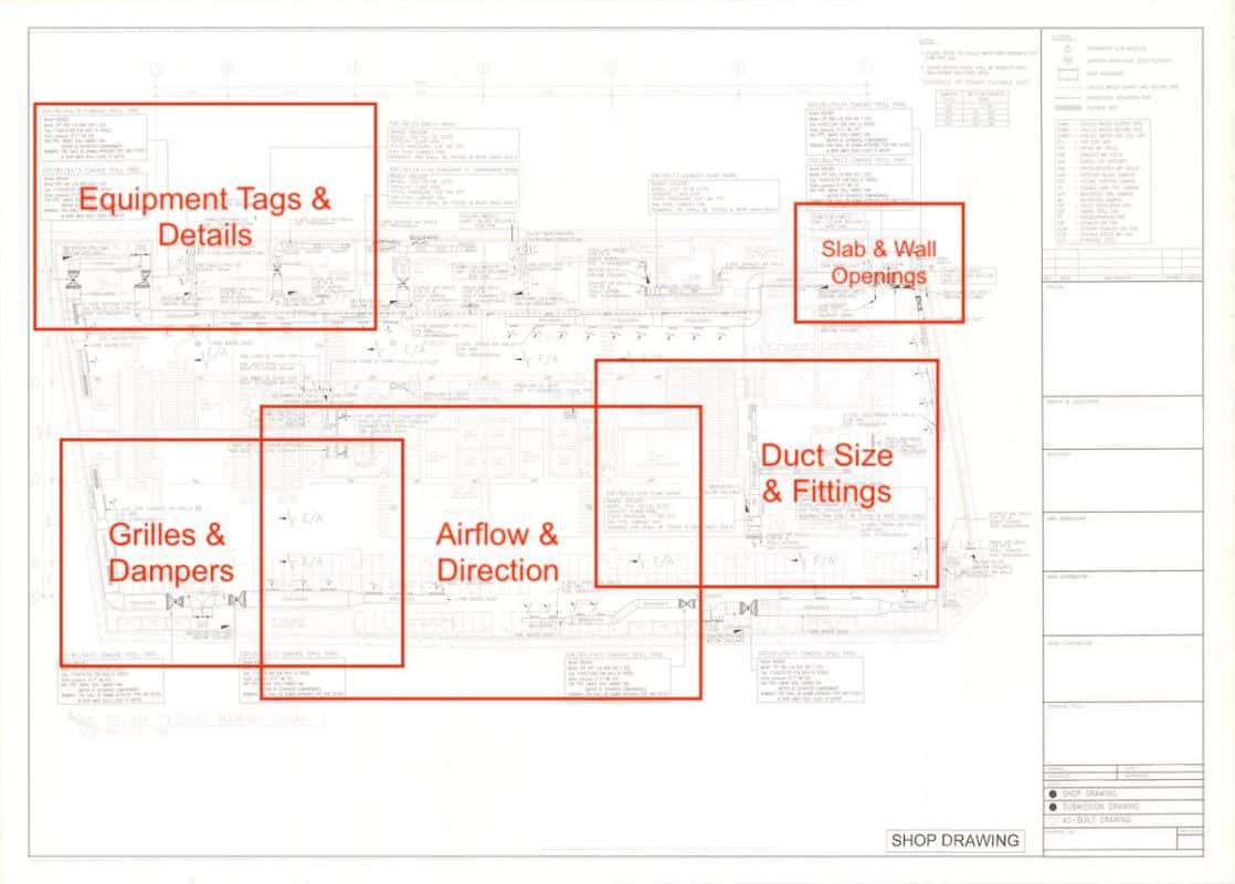
Below is a typical basement smoke extraction ventilation system. I’ll be zooming in to different sections for the explanation. This is for you to follow along easier if you also have the same drawing.
Equipment Tag and Specifications
A good HVAC drawing includes an equipment tag and a few important specifications of the ventilation fan. The equipment tag is usually set by the M&E consultant and you should follow the format to avoid confusion.
Tag Name
Usually, an equipment tag name includes the system, where does it locate, exhaust or fresh air and the fan number. Some tag names are longer depending on the complexity of the project.
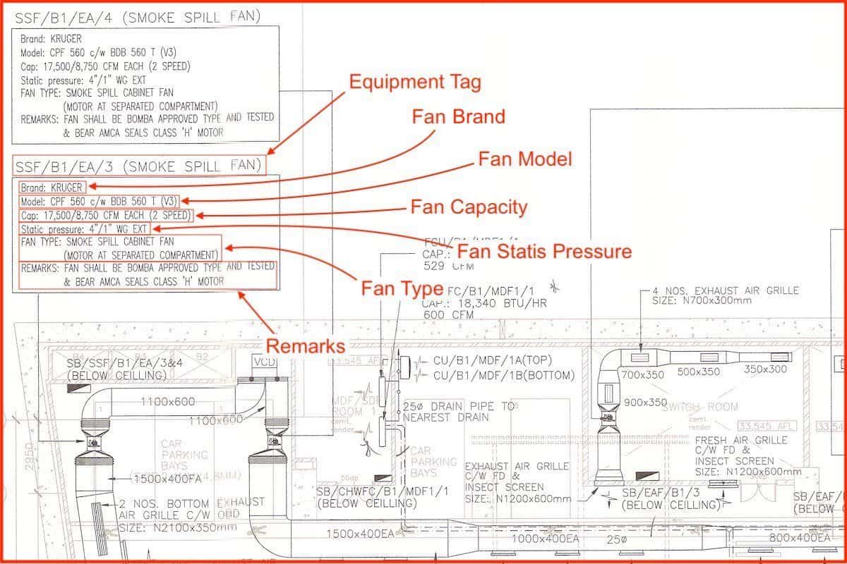
An example of an equipment tag name is shown in the above drawing as: “SSF/B1/EA/3”. It reads as: “Smoke Spill Fan / Basement 1 / Exhaust Air / Fan Number 3”. By reading just the tag name, we know that it is a smoke extraction fan located at basement 1 and there are two more of the same fans.
Specifications
After the equipment tag name, we have a series of specifications that are extracted from the fan’s specification sheet. The reason why we “duplicate” and put them in the shop drawing is that it allows workers to only use shop drawings for installation without having to bring a catalogue along.
Most of the time, such detailed specifications only occur in shop drawings and as-built drawings. Having the fan’s specification stated in shop drawings reduces the chance of installing the wrong one.
Brand and Model
The fan brand and model are straightforward from the catalogue but the model must be precise because some model names are very similar. For instance, CPF500FE vs CPF500FA. A single word difference can mean one has an extra casing and the other one doesn’t.
Capacity
In the above drawing, notice that the capacity is shown as two different airflow rate; 17,500 cfm and 8,750 cfm. It’s because smoke spill fans have two speeds, one for the normal mode and the other for the fire mode.
During the normal mode, smoke spill fans are ventilating the basement space. In case of a fire, these smoke spill fans will run in fire mode to extract smoke out of the basement. Thus, they have two different airflow rates.
Static Pressure
Static pressure also has two different ratings. The fan has 4″ water-gauge (WG) of static pressure in fire mode and 1″ water-gauge (WG) of static pressure in normal mode.
Some static pressures are written as 1 in.WG and it’s the same as 1″ WG. However, some people may prefer to use other units of measurements and you can easily convert them using online unit converters.
The “EXT written after the static pressure indicates that both the 4″ and the 1” WG are EXTERNAL static pressure rather than internal static pressure. External static pressure is the actual static pressure used to push the air instead of overcoming the internal fan motor and blade’s air resistance.
Common acronyms used for different units of measurements for the static pressure are as follow:
| Acronym | Description |
|---|---|
| in.WG | inch of water gauge |
| in.WC | inch of water column (same as WG) |
| in.Aq or in.H2O | inch of water column (same thing) |
| Pa | Pascal (SI Unit) |
| kPa | kilo Pascal |
| psi | Pound per Square Inch (Imperial Unit) |
| atm | Atmospheric Pressure |
Fan Type
Smoke spill fans and other mechanical ventilation fans have many different types to choose from. Each type has its own uniqueness. Some of the common fan types for smoke spill fans are square-shaped cabinet fans (shown in the above drawing), round-shaped axial fans and vane axial fans.
The “motor at separated compartment” written in the above drawing is a remark on the construction of the smoke spill cabinet fan to meet the fire-rated standard. All smoke spill fans are required to run continuously during a fire and thus, they obviously need to be able to work in an extremely high-temperature environment.
Remarks
Remarks are additional information that you want to include for the readers. It’s not compulsory to have but it’s good to have more information. However, we don’t want to jam up the drawing and make it difficult to read.
Duct Size and Fittings
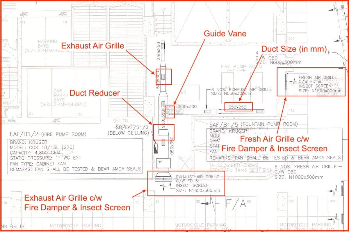
Duct size always starts with the duct width before the duct height. For instance, the above drawing indicated that the duct is 350mm in width and 250mm in height. After each grille, the airflow is reduced inside the duct. So, the duct size should also be reduced using a duct reducer to save cost.
Sometimes, duct size can be written in the imperial unit such as 14×10 (in inches) which is the same thing as 350x250mm (SI Unit). Duct sizes written in feet are less common.
Ideally, the duct should be reduced in size after each grille. However, putting a duct reducer increases the overall installation time. Therefore, you need to strike a balance between installation speed and material cost. More often, having a duct reducer is better.
List of Common Duct Fittings:
- 90 degree bend
- 45 degree bend
- Reducer with slopes on left and right side
- Reducer with slopes on left OR right side only
- Reducer with slopes on top and bottom
- Reducer with slopes on top OR bottom only
Look closely and you’ll see the duct branches out with a slope. That indicates that there is a guide vane inside the duct to better steer the air through the 90-degree bend. Sometimes, guide vanes are drawn as curve lines if there is enough space in the drawing.
Grilles and Dampers
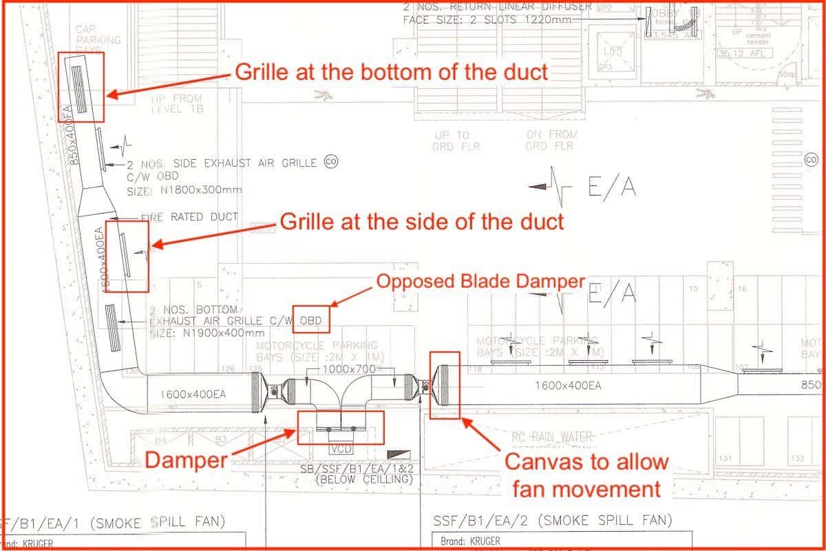
Grilles can be drawn on the duct to indicate bottom air suction/discharge or on the side of the duct to indicate side air suction/discharge. Arrows indicate the direction of the airflow.
Common acronyms used for HVAC ventilation grilles and dampers are as follow:
| Acronym | Description | Function |
|---|---|---|
| EAG | Exhaust Air Grille | Exhausting out air |
| F.A.G. | Fresh Air Grille | Supplying fresh air |
| EAL | External Air Louvre | Exhaust/fresh air louvre at the exterior wall |
| WPEAL | Weatherproof External Air Louvre | Able to prevent rainwater from entering |
| IS | Insect Screen | A steel mesh that prevents insects from entering |
| OBD | Opposed Blade Damper | A basic damper that can alter airflow direction |
| VCD | Volume Control Damper | Adjust airflow manually |
| MFD | Motorized Fire Damper | Automated airflow control via an electrical signal |
| FD | Fire Damper | Close under high temperature automatically |
| NRD | Non-Return Damper | Enable one airflow direction only |
Acronyms are used heavily in engineering drawings so that more information can be included without making them difficult to read.
Some of the common acronyms you may encounter are:
- F.A.G. c/w OBD – Fresh air grille complete with opposed blade damper.
- WPEAL c/w IS – Weatherproof external air louvre complete with insect screen.
On a side note, lines are drawn before and after a fan is known as a canvas. A canvas is some kind of cloth that allows the fan to move and bounce around without pulling/pushing the entire ductwork.
Airflow and Direction
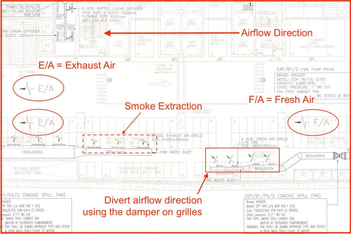
HVAC Ventilation drawings always have arrows to indicate the airflow direction. Some drawings have an airflow rate indicated for installers to meet the requirement through air balancing work.
Some of the common acronyms used for airflow in the HVAC ventilation system are as follow:
- EA = Exhaust Air
- FA = Fresh Air
- OA = Outdoor Air
The common unit of measurements used for HVAC airflow are in the following table:
| Acronym | Description |
|---|---|
| CFM | Cubic feet per minute (Imperial Unit) |
| CMH or m3/hr | Cubic meter per hour (SI Unit) |
| L/min | Litre per minute |
| L/s | Litre per second |
There are many ways to indicate airflow rate but most of the time, CFM and CMH are used in HVAC ventilation drawings to indicate the airflow rate of grilles and fans.
Slab and Wall Openings
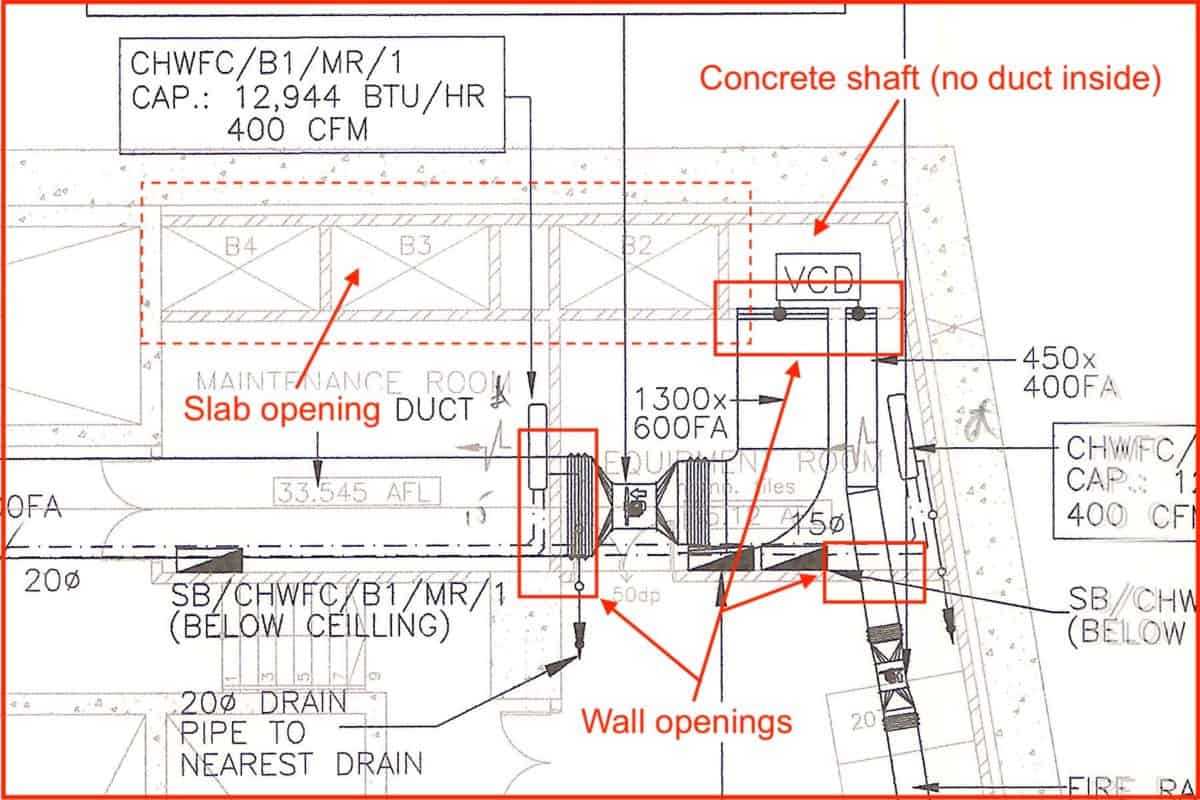
There will be many slab and wall penetrations in the HVAC ventilation system. Whenever a duct passes through a wall, a duct sleeve and a fire damper are needed.
If a duct is not drawn inside a concrete shaft as shown in the above drawing, it means that the air travels inside the concrete shaft, not needing a duct.
Slab and wall openings are the two most important things to pay attention to during the initial stage of construction. Missing openings are very time-consuming and costly to redo. Sometimes, it’s impossible to redo an opening and I’ve seen many junior engineers get screwed hard because of openings including me in the early days.
More posts on how to read HVAC drawings:
Lastly, consider my HVAC Begin (eBook) if you’re a beginner and you want to have a foundational knowledge in HVAC. But, if you have a year or two of experience, then I would suggest you consider my HVAC Basics (eBook). Nonetheless, I encourage you enroll in my HVAC Beginner Course: 10 Days to Become Competent in HVAC if you want to equipped yourself with a complete set of basic HVAC skills.
HVAC Beginner Course
Learn the most basics and foundational HVAC skills including cooling capacity calculation, equipment selection, duct sizing, pipe sizing, exhaust fan sizing, controls, electrical and more.
If you have anything to add (or ask) about this topic, leave a comment down below!