Home VRF System Design Guide with Example and Diagram
The VRF system is getting popular in homes. Many junior engineers are designing a VRF system for their clients. However, they are having a hard time figuring out some of the things involved in the VRF system. Hence, I decided to walk them through the whole VRF system design process and explain all the things involved along the way.
VRF System Basics for Junior Engineers
The VRF or variable refrigerant flow is also known as the VRV system. Both of them are referring to the same thing. Currently, the VRF system has three types; a) air-cooled, b) water-cooled and c) geothermal (not very common). Most of the time, an air-cooled VRF system is used in houses.
As you might have already known, a VRF system generally has one outdoor unit with multiple indoor units, ranging from 3-4 indoor units to 20-30 indoor units or more (maxed at 64 indoor units per system). The indoor unit is available in many different types such as wall-mounted, ceiling cassette and ceiling ducted.
Unlike the multi split system, the VRF system has one set of refrigerant pipes only. A refnet joint is used to connect two sets of refrigerant pipes from two different indoor units. Only one set of refrigerant pipes is connected to the outdoor unit.
Some VRF systems use a BP box (sort of like a refrigerant distribution box) instead of refnet joints. However, these VRF systems are usually low-end or cheap ones.
In terms of pricing, the single split system is the cheapest followed by the multi split system and then, the VRF system before the most expensive air-cooled chiller system. Not involving any water-cooled systems here.
In my opinion, designing the VRF system is all about the right placement for almost everything from the indoor unit to refnet joints, refrigerant pipes and the outdoor unit. Calculating the capacity for the VRF system is no different from other air conditioning systems.
Design a VRF System for a 4BHK Luxury Villa
I have a 4BHK luxury villa floor plan here. I’ll be designing a VRF system from scratch to complete and I’ll walk you through the whole process. Let’s start with the plain drawing as follow:
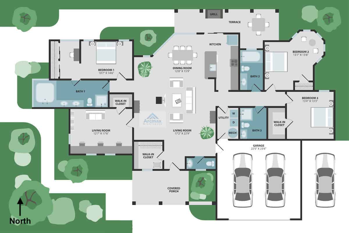
This is a single storey villa with nearly 3,000 sqft. It has 4 bathrooms, 2 living rooms and 1 dining room. Air conditioning is required in all of the 7 rooms with the garage excluded. Besides, the villa’s front door is facing south. So, all bedrooms are either facing east or west and required more cooling capacity.
Following are the selected VRF indoor unit capacity:
| Room | VRF Indoor Unit Capacity |
|---|---|
| Living Room & Dining Room | 40,000 btu/hr |
| Bedroom 1 | 12,000 btu/hr |
| Bedroom 2 | 12,000 btu/hr |
| Bedroom 3 | 12,000 btu/hr |
| Living Room (Small) | 18,000 btu/hr |
| VRF Outdoor Unit | 76,500 btu/hr |
For the living room and the dining room, I combined both rooms and use a 4.0 HP or about 3.5 tons indoor unit. Then, each bedroom is using a 1.5 HP or 1 ton indoor unit. Finally, the small living room will be using a 2.0 HP or 1.5 tons indoor unit.
I use a diversity factor of 20% to size the VRF outdoor unit assuming one of the bedrooms is not occupied when the living and dining room is occupied. Anyway, you should size according to the client’s need.
As for the type of indoor unit, I decided to go for the ceiling ducted unit for the combined living and dining room to give a more premium feel that suits the luxury villa. Besides, clients also preferred to hide the indoor unit as much as possible. The rest of the room will be using the ceiling cassette unit for better air distribution.
The VRF outdoor unit should be located away from the bedroom because it is quite noisy. So, I decided to put it next to the small living room.
Before I move on further, here is the VRF system diagram of my final design:
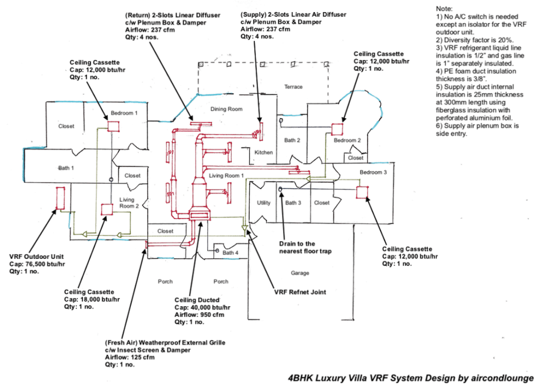
Now, let’s walk through all the elements involved in the above diagram.
VRF Refnet Joint
Generally, you need to have about 600mm of straight length clearance before and after a refnet joint to avoid turbulence that can cause improper refrigerant distribution. Furthermore, all refnet joints should be located where there is clearance for service access.
The most common refrigerant leak spot is at the refnet joint. So, it is wise to ensure that people can access all refnet joints. Not necessarily need a manhole but avoid putting a refnet joint above the cabinet or between the wall where service access is nearly impossible or very difficult.
If you look closely on my diagram, you can see that some refrigerant pipes take a longer route because it needs the straight length that I was talking about and serviceability is taken into account.
Refnet joints used in the VRF system have a specific model. You need to refer to the manufacturer to get the correct refnet joint according to the VRF indoor unit arrangement. The order of the VRF indoor unit is based on its refrigerant pipe length.
Using my above design as an example, the indoor unit in Bedroom 2 is the furthest indoor unit. Hence, it came at last. The next one is Bedroom 3 followed by Living Room 1, Living Room 2 and lastly, Bedroom 1. The sequence of the VRF indoor unit is illustrated as follow:
Bedroom 2 > Bedroom 3 > Living Room 1 > Living Room 2 > Bedroom 1 > Outdoor Unit
Once you fix the refrigerant pipe route, the manufacturer will give you the corresponded refnet joints. If you want to change the VRF indoor unit arrangement, you may need a new refnet joint. The refnet joint models are determined by a capacity formula.
VRF Copper Pipe Wall Thickness
The thickness of the copper pipe for the VRF system is different from the single split system and the multi split system. The VRF system runs at a much higher pressure than the single split system and the multi split system. Furthermore, the pressure test for the VRF copper pipe is also much higher.
The below tables are the copper pipe specification that I used for the VRF system:
| Copper Pipe Size | Copper Pipe Wall Thickness | Insulation Thickness |
|---|---|---|
| 1/4″ (6.35 mm) | 0.61 mm | 1/2″ |
| 3/8″ (9.52 mm) | 0.71 mm | 1/2″ |
| 1/2″ (12.70 mm) | 0.71 mm | 1/2″ |
| 5/8″ (15.88 mm) | 0.81 mm | 1/2″ |
| 3/4″ (19.05 mm) | 0.91 mm | 1/2″ |
| 7/8″ (22.22 mm) | 1.14 mm | 1/2″ |
| Copper Pipe Size | Copper Pipe Wall Thickness | Insulation Thickness |
|---|---|---|
| 1/2″ (12.70 mm) | 0.71 mm | 1″ |
| 5/8″ (15.88 mm) | 0.81 mm | 1″ |
| 3/4″ (19.05 mm) | 0.81 mm | 1″ |
| 7/8″ (22.22 mm) | 0.81 mm | 1″ |
| 1 1/8″ (28.58 mm) | 0.91 mm | 1″ |
| 1 3/8″ (34.92 mm) | 1.07 mm | 1″ |
| 1 5/8″ (41.28 mm) | 1.22 mm | 1″ |
| 2 1/8″ (53.98 mm) | 1.47 mm | 1″ |
Most of the time, both the single split and the multi split copper pipe are using 0.61 mm of copper pipe wall thickness. As you can see from the table, the copper pipe wall for the VRF system is thicker in order to accommodate for the higher working pressure.
Take note that the above table is ONLY APPLICABLE to R-410A refrigerant VRF systems. Different refrigerants will need different specifications. Also, it is for newer air conditioners where the expansion valve is located at the indoor unit.
However, not to worry because most VRF air conditioners are using R-410A and the expansion valve is located in the indoor unit. I have to state the condition to alert the people who are dealing with old VRF air conditioners.
VRF Copper Pipe Insulation Thickness
Typically, the copper pipe insulation thickness for the single split system and the multi split system is either 1/2″ or 3/8″. But, the VRF system needs 1/2″ thick insulation for the discharge line (liquid) and 1″ thick insulation for the suction line (gas). Furthermore, both pipes must be insulated separately.
Separate Power Cable for the Indoor and Outdoor Unit
The indoor unit and the outdoor unit of the VRF system require separate power supplies. So, make sure you have sufficient breakers for all indoor units and the outdoor unit.
No A/C Switches for the VRF System
Do not put any A/C switch for the VRF indoor unit even if the client demands it. VRF indoor units need to communicate with the VRF outdoor unit all the time. If a VRF indoor unit suddenly stops communicating with the VRF outdoor unit, the entire VRF system may stop working and display an error code.
For the VRF outdoor unit, you can put an electrical isolator but you must advise the client never switch off the VRF outdoor unit without you, your company or the manufacturer’s concern. Many VRFs need to redo a series of startup settings every time they restart (power cut off).
However, some newer VRFs are able to restart automatically without the need to do any startup settings and thus, you should check with the VRF manufacturer.
Beware of Signal Cable Interference
The VRF indoor and outdoor units are communicating via a signal cable. Hence, make sure the signal cable is screened and staying away from high power cables to avoid any signal interference which may display different annoying error codes that you have to spend a lot of time dealing with.
Duct Internal Insulation for Noise Suppression
Many engineers have not designed a ceiling ducted air conditioner in a luxury home. Thus, they may miss out on one of the important aspects which is noise reduction. Your client will be very upset if the expensive VRF ducted air conditioner is noisy.
A 4.0 HP or about 3.5 tons ducted unit creates a considerable amount of noise. Many people don’t realize that the noise from the air conditioner is actually transmitted from the supply and return air duct. Thus, we need internal insulation to suppress the noise.
For a small ducted unit, use 25 mm thick fiberglass with perforated aluminium foil on the internal surface of the supply air duct and the return air plenum box will do. Make sure that you use perforated aluminium foil and not the normal flat aluminium foil because you need holes to allow the fiberglass to absorb the noise.
The internal insulation should be about 300 mm in length in the supply air duct. Internally insulate the entire return air plenum box will do. Not necessarily need to go into the return air duct.
Hence, the section of the duct that is internally insulated doesn’t require external insulation anymore. Most clients prefer PE foam insulation for the duct due to being better looking and less harmful. Remember, PE foam is not a good sound absorber, so you can’t use it for internal duct insulation.
Good Ductwork Practices for Luxury Homes
Since you already installing an expensive VRF system for the client, you wouldn’t want to ruin everything with a few bad ductworks.
Use at least 3/8″ thick PE foam insulation on the supply and return air duct. For the fresh air duct, you can use 1/4″ thickness. Besides, the external grille must be weatherproof and with an insect screen to prevent rainwater and insects from entering through the grille.
Many luxury homes with a ducted air conditioner always have the problem with the flexible duct being too long. Generally, a flexible duct should not stretch beyond 1.5 meters. Long flexible ducts have a higher risk of getting bend and choke on the airflow which can cause serious condensation issues.
Speaking of condensation, many homes also have mold and fungus growth problems. Most of the time is due to the oversized air conditioner. So, be aware of it.
I use 2-slots linear diffusers because they generally look good. However, you must be careful with the plenum box attached to the linear diffusers. The flexible duct connection must be from the side of the plenum box rather than from the top to prevent high air velocity.
Besides, each diffuser (especially linear diffusers) should not have an airflow exceeding 250-300 cfm because it’ll start to have audible wind noise. Furthermore, try to put the supply air diffusers away from windows and doors to prevent condensation. You may advise the client to add air curtains for doors that open frequently.
Lastly, don’t forget to put dampers for the ducts.
If you have anything to add (or ask) about this topic, leave a comment down below!


