4 Types of HVAC Drawings and Their Purposes
As HVAC engineers, we have a lot of drawings to read. For junior engineers, it can be intimidating as they don’t know where to start. So, I put together all HVAC drawings and categorized them into 5 types.
Generally, there are 4 types of HVAC drawings which are the HVAC layout drawing, HVAC schematic drawing, installation details for HVAC and single line diagram for HVAC panels. Each type of drawing contains one aspect of the HVAC system.
Some of the drawings are further categorized into a few parts with each part representing one HVAC system. So, without further ado, let’s get into them.
1. HVAC Layout Drawing
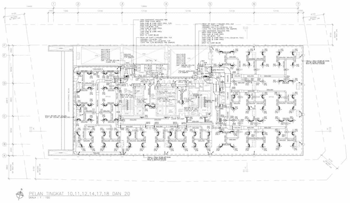
The layout drawing shows the HVAC equipment layout. It is the primary type of HVAC drawing that you’ll be reading a lot. Typically, a high-rise building project consists of around 30 pages of layout drawings with each page representing one floor.
Generally, an HVAC layout drawing has the following content, but not limited to:
- Gridline, scale and dimensions
- Equipment position, quantity and capacity
- Duct size, specification and route
- Grille and diffuser quantity and location
- Flexible duct size and quantity
- Chilled water pipe size and route
- Control panel location and quantity
- Damper type, quantity and location
- Thermostat location and quantity
Most of the time, layout drawings are used to see the location of the HVAC equipment. Besides, they are useful for site coordination to prevent clashes of services.
Furthermore, equipment capacity can be found on layout drawings. Grilles, diffusers, control panels and other equipment must be drawn exactly as per the required quantity on the layout drawings. Otherwise, the HVAC contractor has the right to claim for variations.
In the meantime, I would like to inform you that you can learn quicker by getting my HVAC Begin (eBook) if you’re a beginner. But, if you have a year or two of experience, then I would suggest you consider my HVAC Basics (eBook). Nonetheless, I encourage you enroll in my HVAC Beginner Course: 10 Days to Become Competent in HVAC if you want to equipped yourself with a complete set of basic HVAC skills.
HVAC Beginner Course
Learn the most basics and foundational HVAC skills including cooling capacity calculation, equipment selection, duct sizing, pipe sizing, exhaust fan sizing, controls, electrical and more.
2. HVAC Schematic Drawing
The schematic drawing is the second most important type of HVAC drawing. Usually, a medium-scaled project has a few schematic drawings with each drawing representing one HVAC system.
I always use schematic drawings to understand the HVAC system of new projects. Besides, schematic drawings are great for counting materials and forming a bill of material (BOM).
a) Chilled Water Piping
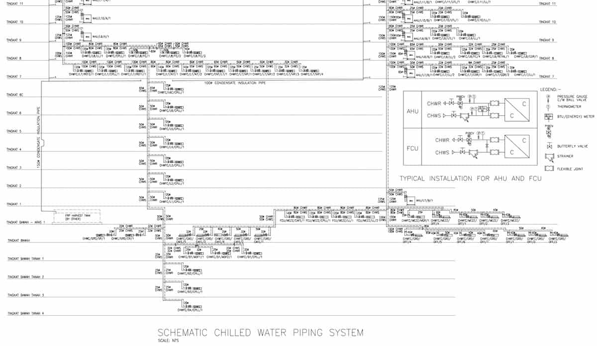
For the chilled water system, you’ll have a schematic drawing for the chilled water piping. A typical chilled water piping schematic will show you the chilled water pipe and the condenser water pipe connection from chillers and pumps to air handling units and cooling towers.
From the chilled water pipe schematic, you can see all the required valves, accessories (pressure gauges, temperature gauges, etc.) and pipe fittings. Again, they need to be drawn to the exact quantity or else, HVAC contractors may claim for variations.
Furthermore, you can learn how the chilled water pipes run from floor to floor, equipment to equipment, including their sizes by studying the schematic drawing. Moreover, the drawing indicates which line is the supply and which is the return.
b) Pressurization System
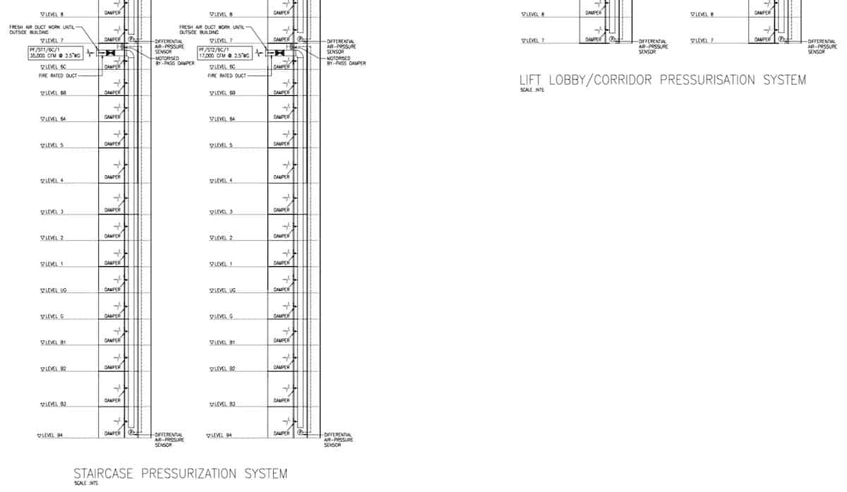
Most HVAC projects have a pressurization system and thus, you’ll have a schematic drawing for the pressurization system, especially when it is a high-rise building.
From the pressurization schematic, you can identify the location and quantity of pressurization grilles and dampers. Furthermore, you can see where is the pressure differential sensor located which is very important for the performance of the system.
Moreover, you can confirm whether the pressurization system is using concrete shafts without ducts or ducts are required to be installed inside the concrete shafts. Then, other information such as fan airflow and static pressure can be found from the schematic.
c) CO2 Sensor System
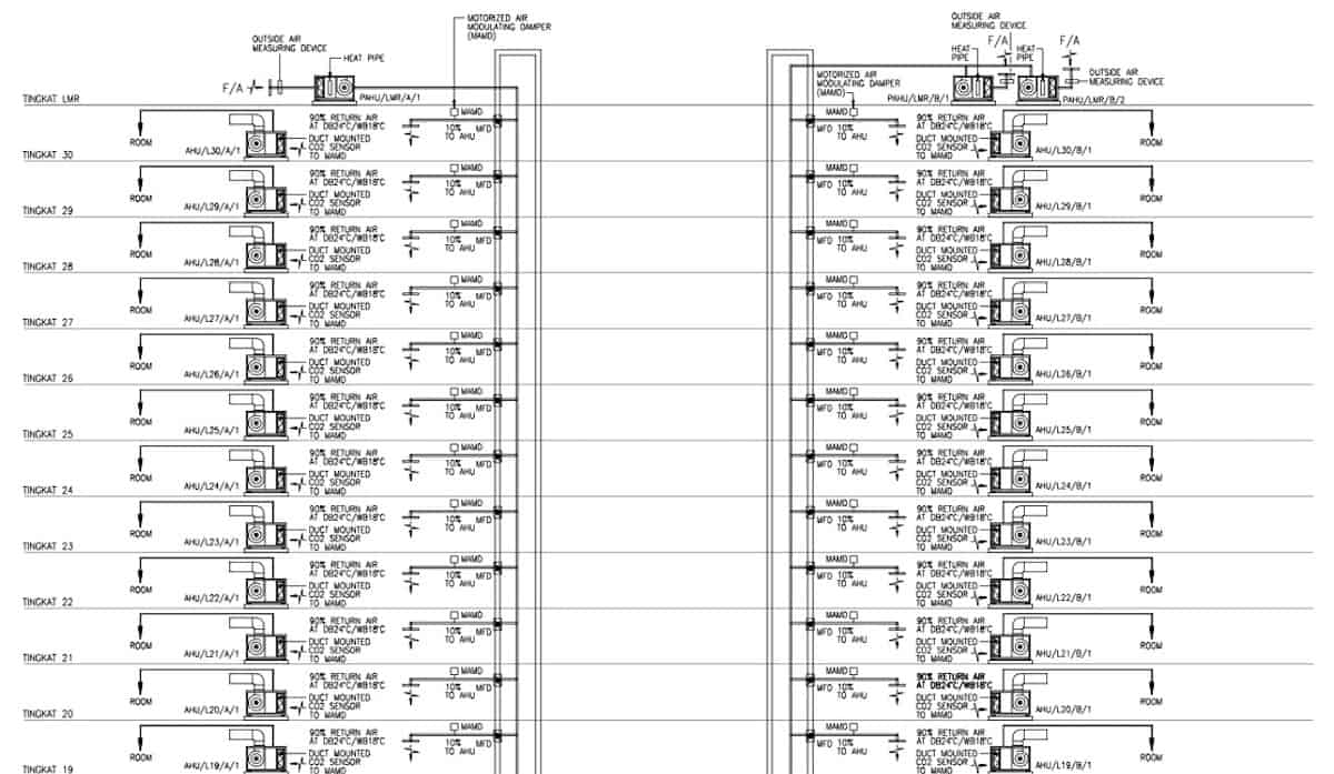
If you have pre-cool air handling units (PAHUs), you may have a schematic drawing for the CO2 sensor system. This schematic drawing will show you the design of the CO2 sensor system.
From the CO2 sensor schematic, you may find the design condition, damper configuration and sensor location. Often, you get to learn how the CO2 sensor system works by studying the schematic drawing.
3. Installation Details for HVAC
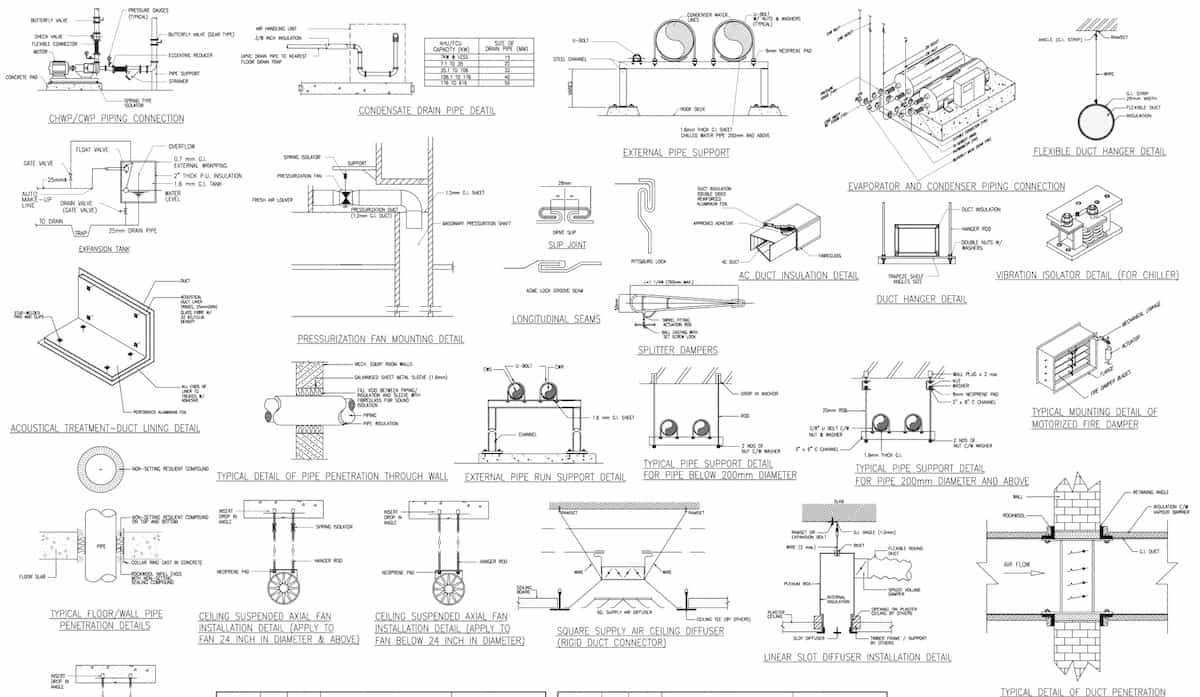
Installation details are drawings that show the installation method and specification. They are usually issued by design engineers or consultants. Nonetheless, they are based on international standards such as SMACNA (for ducts).
However, some installation details are based on practices and experiences. They serve as guides for HVAC contractors to follow. But, HVAC contractors can always submit their proposed installed method and details for the approval of the consultant.
4. Single Line Diagram for HVAC Panels
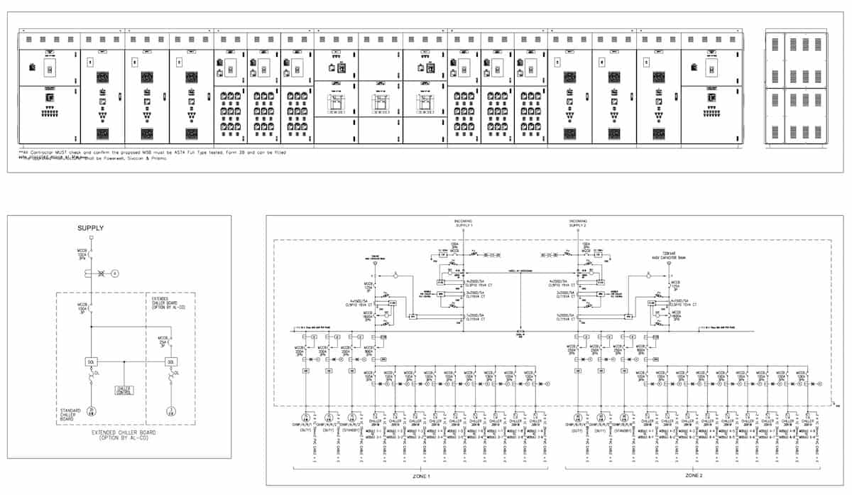
Control panels are essential for the HVAC system and hence, single line diagrams are inevitable. Single line diagrams show the wiring details of the control panels. Specifications such as cable sizes and breaker sizes are written in single line diagrams.
Design engineers or consultants may issue single line diagrams to HVAC contractors but, HVAC contractors can always submit their single line diagrams for the approval of the consultant.
Other Drawings Relevant to HVAC
- Opening Drawing – Used to show wall and slab opening details for pipes and ducts penetration.
- Section Drawing – Used to show more details about a particular installation in side view.
- Elevation Drawing – Used to show floor to floor height. Useful for pipes and ducts length estimation.
Types of Construction Drawings Related to HVAC
- Tender Drawing – For HVAC contractors to bid for the job.
- Construction Drawing – As a guide for HVAC contractors to build the HVAC system. Issue by consultants.
- Shop Drawing – For HVAC contractors to actually build the HVAC system. Approved by consultants.
- As-Built Drawing – Complete by HVAC contractors based on the actual installation. Approved by consultants.
If you want to learn how to read HVAC drawings in detail from air conditioning systems to control panel diagrams, check out my 5 courses blog post starting with title blocks & symbols.
Lastly, consider my HVAC Begin (eBook) if you’re a beginner and you want to have a foundational knowledge in HVAC. But, if you have a year or two of experience, then I would suggest you consider my HVAC Basics (eBook). Nonetheless, I encourage you enroll in my HVAC Beginner Course: 10 Days to Become Competent in HVAC if you want to equipped yourself with a complete set of basic HVAC skills.
HVAC Beginner Course
Learn the most basics and foundational HVAC skills including cooling capacity calculation, equipment selection, duct sizing, pipe sizing, exhaust fan sizing, controls, electrical and more.
If you have anything to add (or ask) about this topic, leave a comment down below!


