How to Read HVAC Drawings? (Title Block & Symbols)
I learned to read different kinds of HVAC drawings through years of working in the HVAC industry. I thought if junior engineers are able to know how to read HVAC drawings earlier, they are able learn faster. So, how do you get started on HVAC drawings?
To read HVAC drawings, start by understanding the drawing title block. Next, identify whether the HVAC drawing is a layout, section, elevation or schematic drawing. Then, understand the meaning of the symbols used in HVAC drawings.
Many junior engineers start reading HVAC drawings without first understanding what is the drawing about. By knowing the meaning of the drawing first, you can understand it better.
Title Block
Title block is the standard cover for HVAC drawings. It contains information about the drawing type, the legend, the project title, related companies and more.
Notes and Legend

This section of the drawing consists of notes such as disclaimers, things to highlight and how to read the drawing. Also, HVAC symbols and legend are usually included in this section to help readers to understand the drawing.
Some consultants write detailed specifications extracted from the original tender contract here such as duct insulation thickness and support bracket materials
This section is often neglected by many junior engineers. I always suggest junior engineers read this section carefully because sometimes, important information can be found there.
Drawing Revision Table

This section of the drawing is to record all changes made to the drawing. It’s a simple table that tracks the past changes made to the drawing.
| – | – | – |
| – | – | – |
| 02 | 5 nos. grilles added as requested | 8/7/20 |
| 01 | Duct size revised as per clouded | 4/5/20 |
| Rev | Description | Date |
It’s important to update the drawing revision table every time a drawing is revised. However, the majority of the people are skipping this step, making the change history of a drawing difficult to track.
Project Title
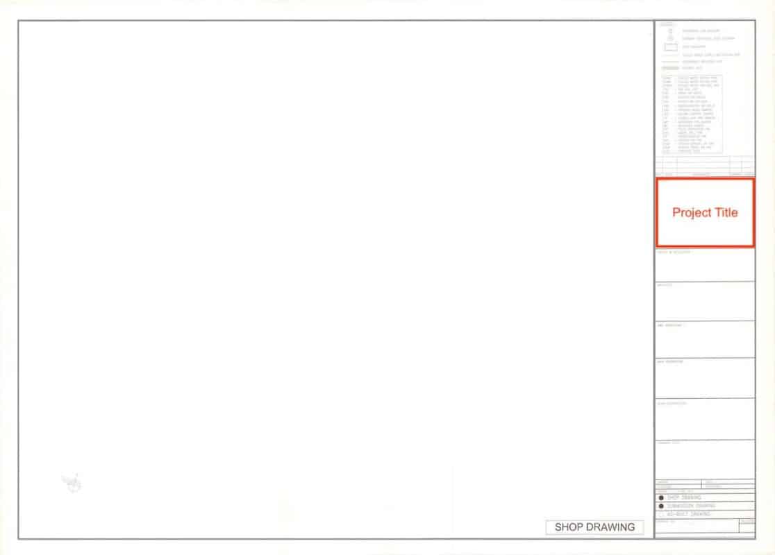
As the name suggests, this section is to put down the full project title. For a construction project, a full project title should NOT be something like: “Malaysia KLCC Petronas Twin Tower”.
Instead, a proper project title should be something like: “Construction of 88-storey twin-tower office buildings on LOT 1957 with 31 floors of office spaces, 8 floors of commercial retail stores…”.
Readers should be able to get a grasp of what this project is about by just looking at the project title. However, the project title is mostly set by the project owner or the architect and you can’t change anything.
Related Companies
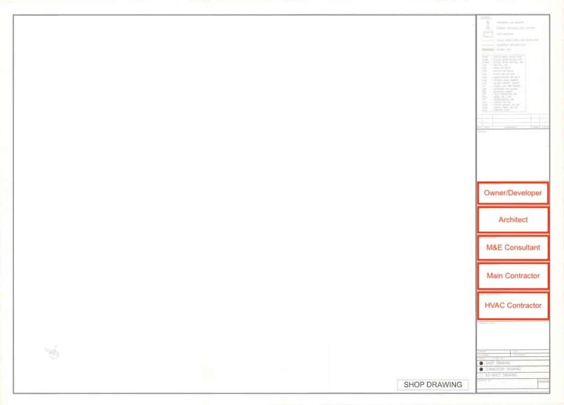
This entire section includes all companies involved in the project. For a construction project, the top of the line should be the owner or developer followed by the architect, the M&E consultant, the main contractor and finally, the contractor who prepares the drawing. In this case, the HVAC contractor.
Each section should include company details such as a logo, company name, company address and company contacts (phone number, website address, fax number and email address). A person’s name is usually not included in this section.
Drawing Title and File Name
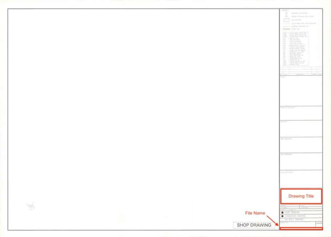
The drawing title section is meant to put a clear name for the drawing. The drawing title should have the floor number, the room name and the equipment or system involved.
Drawing title examples:
Level 6 – Elevated Carpark
Smoke Control System Layout Drawing
Basement 2 – Lift Lobby 1
Fan Coil Unit Section Drawing
It’s a good practice to have a small section for the actual file name in the company’s server for own-self tracking. The file name could be something like: “CDRIVE/PROJECT/KLCC/SHOPDWG/L6”.
In the meantime, I would like to inform you that you can learn quicker by getting my HVAC Begin (eBook) if you’re a beginner. But, if you have a year or two of experience, then I would suggest you consider my HVAC Basics (eBook). Nonetheless, I encourage you enroll in my HVAC Beginner Course: 10 Days to Become Competent in HVAC if you want to equipped yourself with a complete set of basic HVAC skills.
HVAC Beginner Course
Learn the most basics and foundational HVAC skills including cooling capacity calculation, equipment selection, duct sizing, pipe sizing, exhaust fan sizing, controls, electrical and more.
Drawing Credits and Date
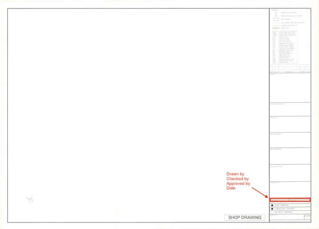
This section often is a small table about who draws the drawing, the checker, the approver and the respective dates. The approver does not necessarily mean the drawing is approved but rather the way it is drawn is accepted for submission.
This section is usually for own-self tracking. The company responsible for the drawing is able to know that the drawing is drawn by who, who had checked it and who gave the permission to submit.
Drawing and Revision Number
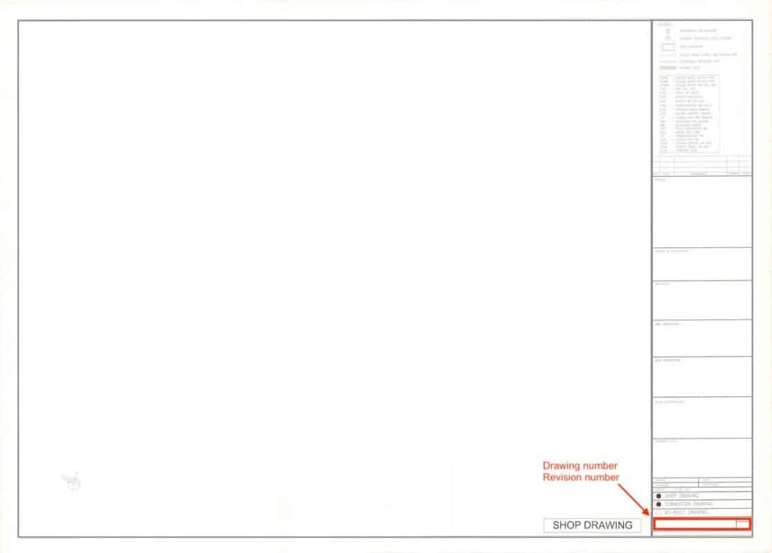
This is an important section that indicates the drawing number and the revision number. A drawing number is a running number that somewhat represents the category or type of the drawing. An example of the drawing number is: “KLCC/HVAC/SHOPDWG/L6”.
The revision number is exceptionally important to keep everybody updated. Without the revision number, readers will have a hard time figuring out which drawings are the latest ones.
Some people like to put the drawing number with the revision number included. An example is: “KLCC/HVAC/SHOPDWG/L6/01”.
Most of the time, the drawing number starts with the shorten project name followed by the service/system, the drawing type, the floor number and finally, the revision number. However, it can be written in other formats and it’s all depending on the project.
It’s advised that you always follow a standard format set by the architect or the M&E consultant to avoid any misinterpretation and confusion.
Drawing Type
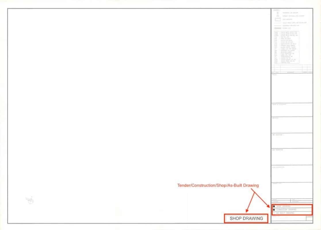
The type of the drawing must always be indicated but not necessarily positioned as per the above drawing. There are mainly 4 types of drawings; a) tender drawing, b) construction drawing, c) shop drawing and d) as-built drawing.
The drawing type must be clearly indicated so that readers know exactly what they are looking at. Different drawing types have drastically different meanings.
List of drawing types and their purpose:
- Tender Drawing – Produced by the architect, the M&E consultant and other designers for installers/contractors to tender/bid the project based on tender drawings.
- Construction Drawing – Produced by the M&E consultant and other designers after the tender process for appointed installers/contractors to prepare shop drawings. The construction drawing may or may not be the same as the tender drawing depending on whether or not something need to be changed along the process.
- Shop Drawing – Prepared by installers/contractors for the approval of the M&E consultant in order to construct/install according to approved shop drawings.
- As-Built Drawing – Prepared by installers/contractors for the approval of the M&E consultant based on what have been constructed/installed. As-built drawings are binded in the operation manual and maintenance of a completed building for the reference of the owner of the building.
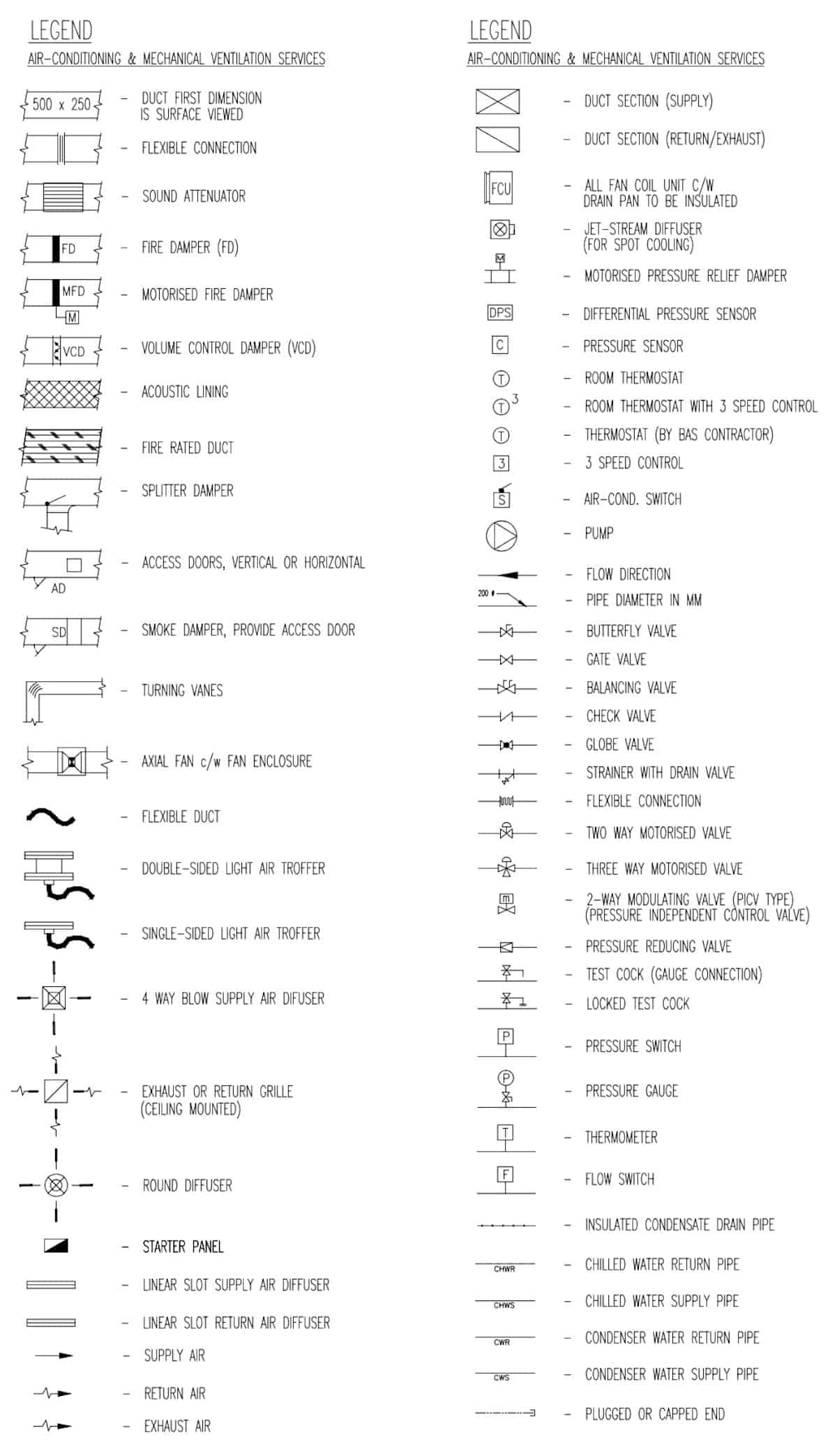
List of HVAC Symbols
HVAC symbols are drawn in many different forms and shapes based on local preferences. However, they should not be drawn too differently. Hence, readers should always refer to the legend or the table of symbol and description.
Some of the HVAC symbols and their meaning as follow:
Section Drawings
Layout drawings are difficult to present height which is a very important metric in construction. Furthermore, riser/dropper pipes and ducts are impossible to visualize in layout drawings. Hence, section drawings are needed.
A section drawing starts in a layout drawing by slicing through a particular area in the layout drawing to represent the view of the section drawing. Then, readers need to refer to a separate drawing to see the side view of that particular area.
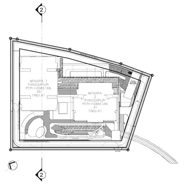
To give you an example, the above drawing shows that a section is cut through a building. Usually, such a section drawing is labeled as “Section 2-2”. The symbol used for the section cut is a number or an alphabet inside a circle attached to a filled triangle pointing towards the view of the section.
A section cut can be just one symbol but it’s much better to have two symbols stretching across the section view that you wish to present in a separate section drawing. Sometimes, small section views can be presented in a corner of the same layout drawing.
The line connecting the two symbols can be a solid line or dotted line depending on your preference. I prefer to use a solid line and I usually draw the symbol sort of like an eye because it looks better.
Gridlines
In a section drawing, gridlines are advisable to include if the section cut is substantial. For example, if you are cutting through a building or the entire chiller plant room, you should include gridlines for readers to understand easier.

Sometimes, a section view can have many different structures and equipment. Maintaining gridlines in section drawings helps people to read faster.
Section drawings follow the same principle as layout drawings. Things drawn in a section drawing must be scaled. Section drawings are considered as detail drawings where workers are used for construction. In addition, section drawings should have dimensions clearly indicated.
Section Drawings within a Section Drawing
A section drawing within a section drawing can be done when a particular work is very complicated. Although it is generally better to have fewer section drawings, complex works are often better to show in separate section views so that people can read each section drawing better.
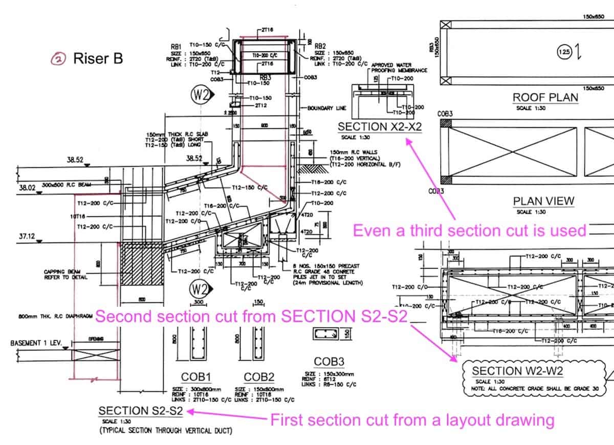
In the above example, it is impossible to show every detail in one section drawing. Thus, section drawings within a section drawing are necessary to present all information. The above section drawing is one of the section drawings that I previously worked on together with other engineers. It’s a basement smoke extraction shaft.
Differentiate Section and Schematic Drawings
Not all side views are section drawings. Generally, section drawings should be scaled. On the other hand, schematic drawings are not scaled and are often used to illustrate the components of a system. Because there are so many components involved, put everything to scale in a schematic drawing is not practical.
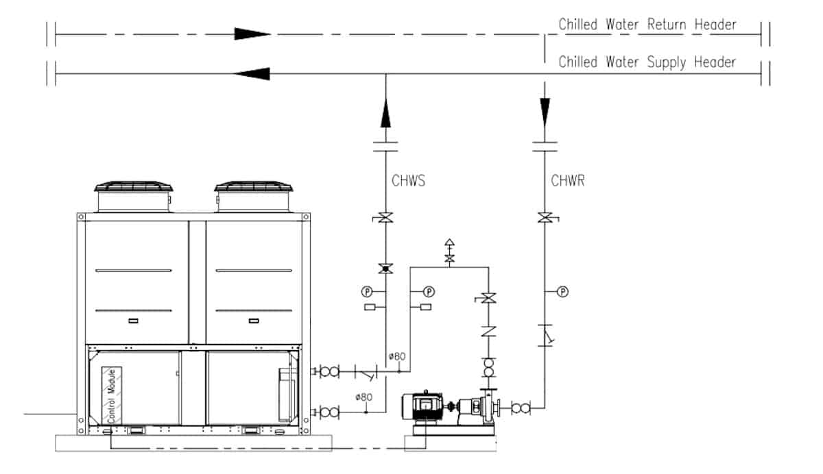
Some people may consider the above drawing as a section drawing but I consider it as the side view of a schematic drawing. It posses the characteristic of a schematic drawing which is drawn in single-line and not-to-scale.
Schematic Drawings
Schematic drawings are used to illustrate the design aspect of a system rather than using them for installation works. While layout and section drawings are used by workers, schematic drawings are mostly used by engineers.
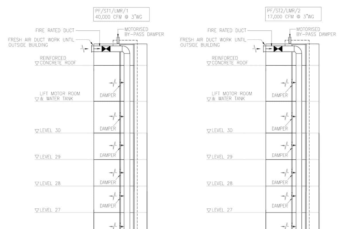
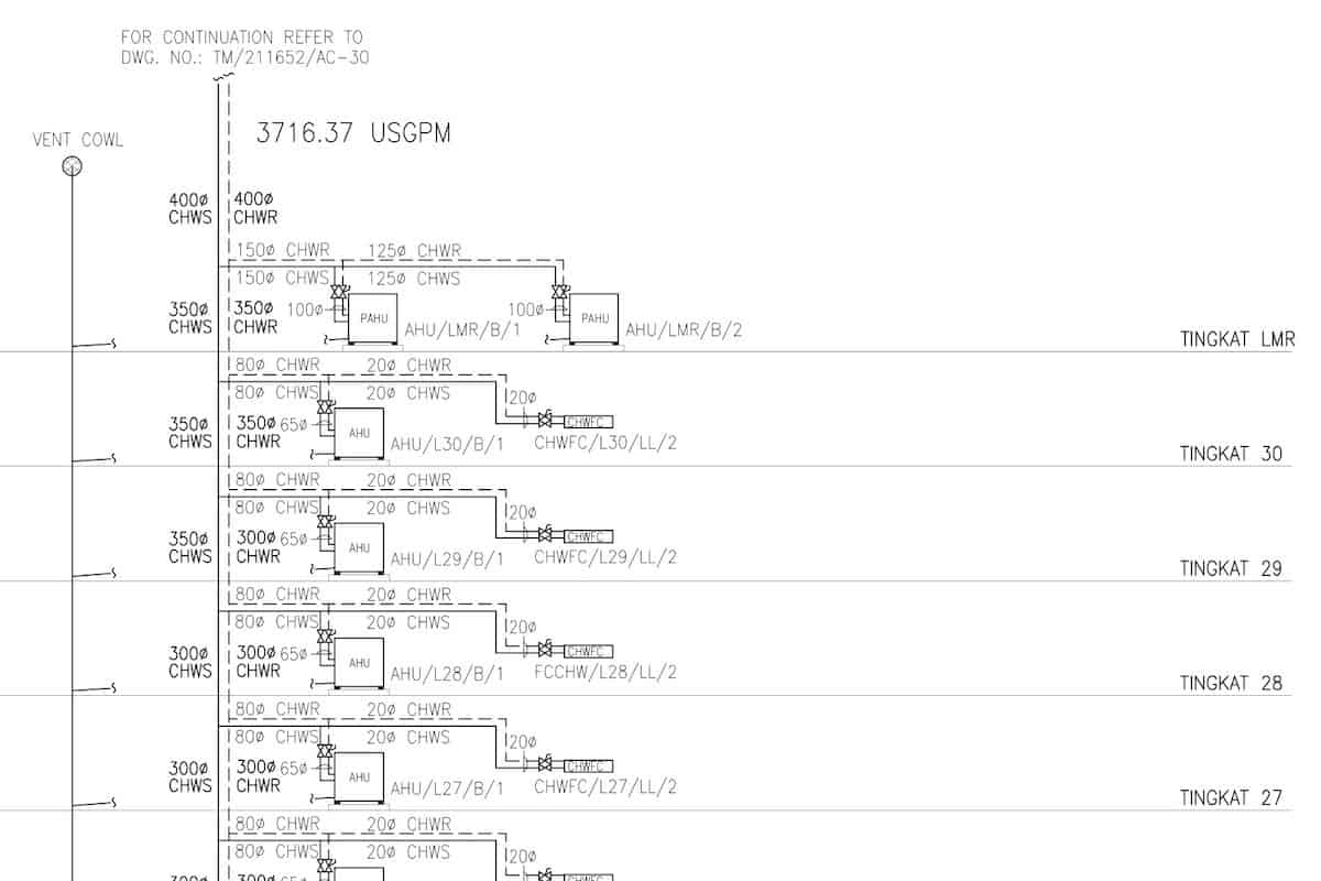
Most of the things drawn in a schematic drawing are presented in single-line and not-to-scale in order to fit in as much information as possible. Riser/dropper pipes and ducts are two major HVAC systems that will always have a schematic drawing.
Schematic drawings are also best to represent how the system works. A chilled water HVAC system can quickly become overwhelming to an engineer who is trying to understand it on 20-30 pages of layout drawings. However, by looking at 2-3 pages of schematic drawings, the engineer is able to understand the entire system relatively faster.
Sometimes, a schematic drawing can help us to understand the building height since most schematic drawings included the floor-to-floor height and floor levels. However, a better representation of a building’s appearance and height is elevation drawings.
Elevation Drawings
Many people confuse elevation drawings with section drawings. An elevation drawing can have a side view just like a section drawing but the elevation drawing doesn’t cut through half way. Elevation drawings show the outer appearance and dimension of a building.

Elevation drawings are seldom used by HVAC engineers. Some HVAC engineers don’t even know such drawings existed. When designing the location for outdoor units, elevation drawings are very handy.
If you want to see more elevation drawing examples, refer to your house sales and purchase agreement where you’ll find the front, back, left and right elevations of your landed house.
More posts on how to read HVAC drawings:
Lastly, consider my HVAC Begin (eBook) if you’re a beginner and you want to have a foundational knowledge in HVAC. But, if you have a year or two of experience, then I would suggest you consider my HVAC Basics (eBook). Nonetheless, I encourage you enroll in my HVAC Beginner Course: 10 Days to Become Competent in HVAC if you want to equipped yourself with a complete set of basic HVAC skills.
HVAC Beginner Course
Learn the most basics and foundational HVAC skills including cooling capacity calculation, equipment selection, duct sizing, pipe sizing, exhaust fan sizing, controls, electrical and more.
If you have anything to add (or ask) about this topic, leave a comment down below!


