Chiller Capacity Calculation: Formula, Example, TR & kW
Chiller capacity is usually shown in the brochure or specification sheet. However, after the installation, the chiller may operate in different conditions and some people may need to re-calculate the capacity for various reasons.
In general, chiller capacity is calculated using the heat transfer formula Q = mcθ where Q is the chiller capacity, m is the chilled water mass flow rate, c is the specific heat capacity of water and θ is the chilled water supply-return temperature difference.
Although chiller capacity can be calculated using a simple formula, there are a few measurement units used for chiller capacity. Hence, some people are confused about it.
Chiller Capacity Formula
In total, there are 2 measurement units commonly used for chiller capacity as follows. Other measurement units can be found in my previous blog post.
| Acronym | Chiller Capacity |
|---|---|
| TR | Tons of Refrigeration |
| kW | kilowatt |
Among the two, TR or tons of refrigeration is more common than kW or kilowatt. Take note that kW is referring to chiller capacity in this case, not to confuse it with the kW used for electrical power.
TR is actually derived from BTU which stands for British Thermal Unit and one TR is equivalent to 12000 BTU. Meanwhile, one kW is equivalent to 3412 BTU.
Chiller capacity expressed in BTU is the result of the heat transfer formula practiced in the Imperial unit. If you’re using the SI unit, the heat transfer formula will provide you with the chiller capacity in kW.
Imperial Unit
Many people are using the Imperial unit for chiller capacity, including myself. I find it easier to say it that way as kW is normally used for electrical power.
Now, let’s take a closer look at the heat transfer formula using the Imperial unit:
Q = mcθ
where,
Q = chiller capacity, btu/hr
m = chilled water mass flow rate, lb/hr
c = specific heat capacity of water, btu/lb.°F
θ = chilled water supply-return temperature difference, °F
In practice, we use devices to measure the chilled water flow rate, not the mass flow rate directly. So, we need to use the following formula to get the m:
m = ρV
where,
ρ = density of water, lb/ft3
V = chilled water flow rate, ft3/hr
The chilled water flow rate measured by devices such as ultrasonic flow meters may be expressed in ft3/hr, ft3/min or ft3/s. So, you’ll need to convert it to ft3/hr for the formula.
| Feet per Second | Feet per Minute | Feet per Hour |
|---|---|---|
| 1 ft3/s | 60 ft3/min | 3600 ft3/hr |
Now, if we put it all together, the chiller capacity formula becomes the follow:
Q = ρVcθ
Q = (lb/ft3)(ft3/hr)(btu/lb.°F)(°F)
Q = btu/hr
Once you’ve calculated the Q in btu/hr, simply divide it by 12000 to convert it into TR.
TR = btu/hr ÷ 12000
If you want to get the chiller capacity in kW, simply divided the btu/hr by 3412.
kW = btu/hr ÷ 3412
But, if you’re not practicing the Imperial unit and you use the SI unit, the following is the same procedure expressed in the SI unit.
To convert from IP to SI unit, use my HVAC Online Unit Converter.
SI Unit
I can see that more and more people are leaning toward the SI unit. After all, it can standardize the measurement unit used in the HVAC industry.
This time, let’s look at the heat transfer formula using the SI unit:
Q = mcθ
where,
Q = chiller capacity, kW
m = chilled water mass flow rate, kg/s
c = specific heat capacity of water, kJ/kg.°C
θ = chilled water supply-return temperature difference, °C
Again, consider that we use devices to measure the chilled water flow rate, not the mass flow rate directly. So, we need to use the following formula to get the m as well, but in the SI unit:
m = ρV
where,
ρ = density of water, kg/m3
V = chilled water flow rate, m3/s
Similarly, the chilled water flow rate measured by devices such as ultrasonic flow meters may be expressed in m3/hr, m3/min or m3/s. So, you’ll need to convert it to m3/s for the formula.
| Meter per Second | Meter per Minute | Meter per Hour |
|---|---|---|
| 1 m3/s | 60 m3/min | 3600 m3/hr |
Take note that in the SI unit, the chilled water flow rate is per second, not per hour. It is because the chiller capacity in kW is actually kJ/s (1 kJ/s = 1 kW). So, the flow rate needs to be m3/s.
Now, if we put it all together once again, the chiller capacity formula becomes as follow:
Q = ρVcθ
Q = (kg/m3)(m3/s)(kJ/kg.°C)(°C)
Q = kJ/s = kW
Once you’ve calculated the Q in kW, you also can multiply it by 3412 to convert it into btu/hr and then divide it by 12000 to convert it into TR. Else, you also can divide the kW by 3.52 (12000 ÷ 3412 = 3.52) to convert it into TR.
btu/hr = kW x 3412
TR = btu/hr ÷ 12000
TR = kW ÷ 3.52
On a side note, if you want to quickly learn about chilled water system, you can get my Chilled Water System (eBook). If you’re into design, you can enroll in my Chilled Water System Design Course where I teach you various design procedures with tons of examples.
Chilled Water System Design Course
Learn how to design a chilled water system with AHU/FCU selection, chiller sizing, cooling tower sizing, pump sizing, piping design, ductwork design and more.
Chiller Capacity Calculation Example
New chilled water systems have a built-in monitoring system that can show chiller capacity in real time. However, how do you calculate chiller capacity for old systems that don’t have a monitoring system?
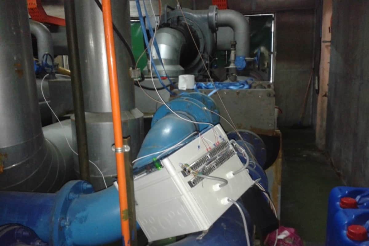
To calculate chiller capacity the manual way as a part of the energy audit exercise, you’ll need the following devices:
- Water flow meter (eg: ultrasonic flow meter c/w data logger)
- Temperature sensor (eg: RTD sensor c/w data logger)
From the heat transfer formula, we need to measure the chilled water flow rate and the chilled water supply-return temperature difference in order to calculate the chiller capacity. The rest of the variables in the formula are fixed as follow:
| Variables | Imperial Unit | SI Unit |
|---|---|---|
| Density of water, ρ | 62.4 lb/ft3 | 1000 kg/m3 |
| Specific heat capacity of water, c | 1 btu/lb.°F | 4.2 kJ/kg.°C |
Now, let me show you an energy audit exercise that I once did for the chilled water system in a hospital and then, we calculate the chiller capacity from there.
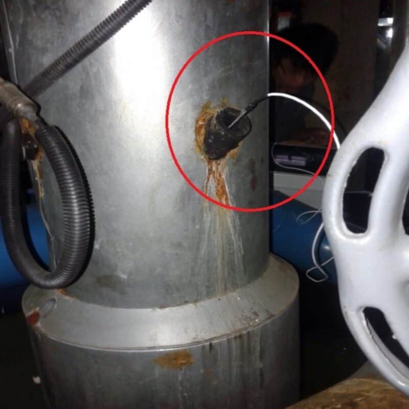
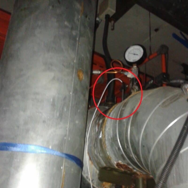
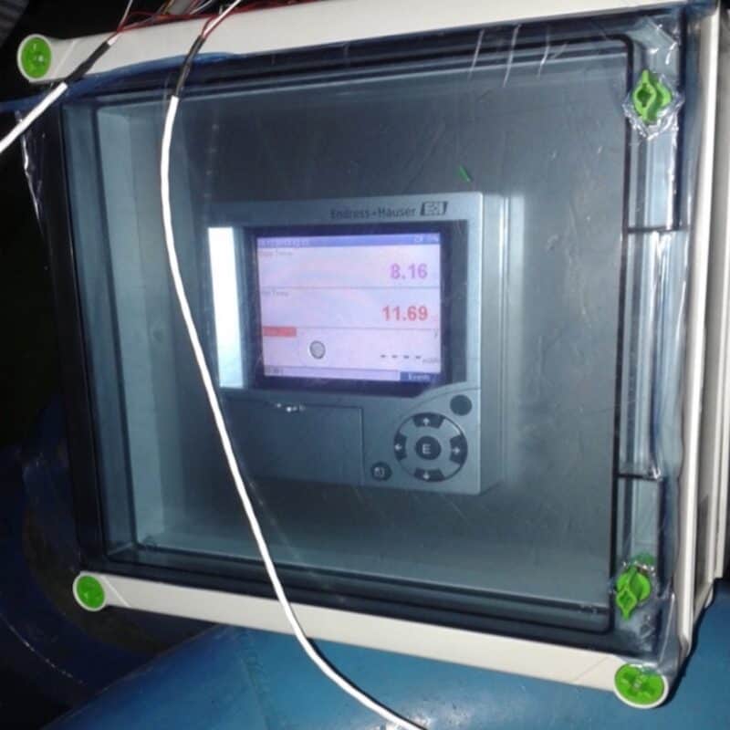
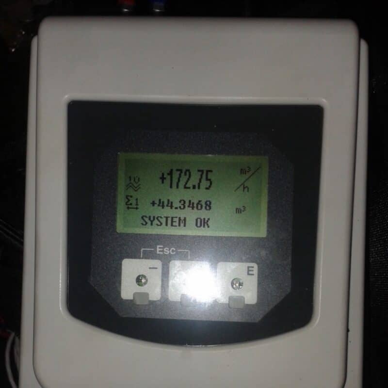
To see 24 hours chiller capacity data, you will need to log the temperature and flow rate for 24 hours. For this example, I’ll use instantaneous data.
From the temperature data logger, the chilled water supply and return temperatures and flow rate are as follow:
| Measurements | Results |
|---|---|
| Chilled water supply temperature | 8.16°C (46.68°F) |
| Chilled water return temperature | 11.69°C (53.04°C) |
| Chilled water flow rate | 172.75 m3/hr (6100.6 ft3/hr) |
Using the heat transfer formula in the SI unit, the chiller capacity can be calculated as follow:
Q = ρVcθ
Q = (1000)(172.75/3600)(4.2)(11.69-8.16)
Q = 711.44 kW
Q = 711.44 ÷ 3.52
Q = 202 TR
If we convert everything into the Imperial unit, we can calculate the chiller capacity as follow:
Q = ρVcθ
Q = (62.4)(6100.6)(1)(53.04-46.68)
Q = 2,421,108.51 btu/hr
Q = 2,421,108.51 ÷ 12000
Q = 202 TR
There you have it. With a little bit of measurement, you can study the chiller capacity and then compare it with the design capacity. Afterward, you may proceed with the diagnosis, optimization or upgrade as necessary.
Just be careful with the measurement. Make sure to follow the proper way of inserting the RTD sensor and installing the flow meter to ensure the result is accurate. Also, don’t forget to calibrate your devices beforehand.
New Design Chiller Capacity Calculation
Now, what if you’re not dealing with old chillers but attempting to design new chillers? How do you calculate the required chiller capacity?
First, you need to estimate the water flow rate. For that, read my post on chilled water flow rate calculation and condenser water flow rate calculation.
Assuming that the building you’re designing has a cooling load requirement of 2000 RT. To calculate the chiller capacity needed, you need to analyze the building’s load profile to identify the low and peak cooling load throughout the day.
Basically, you need to project a load profile.
For example, if the cooling load is 2000 RT, the first chiller combination comes to mind is 4 nos. of 500 RT chillers. However, if it is an office building and before working hour, only the common areas need cooling and hence, the low cooling load is 200 RT and if you only have a 500 RT chiller, it’ll run at 40% part load which is not efficient.
In this case, it make sense to use something like 1 x 200 RT plus 3 x 600 RT chillers. That way during low load conditions, the 200 RT chiller will still be running efficiently.
Once again, you can get my Chilled Water System (eBook) to quickly learn more about chilled water system. But, if you want to learn how to design a chilled water system from start to end, I encourage you check out my Chilled Water System Design Course.
Chilled Water System Design Course
Learn how to design a chilled water system with AHU/FCU selection, chiller sizing, cooling tower sizing, pump sizing, piping design, ductwork design and more.
If you have anything to add (or ask) about this topic, leave a comment down below!


