What is Bypass in Chilled Water Systems?
Whether you are a design engineer, project engineer, operator or maintenance personnel, I’m sure you heard of the word/term bypass when dealing with chillers and chilled water systems. So, what exactly is the bypass that people always talk about?
In chilled water systems, bypass is a mechanism that is commonly used to maintain the minimum flow of chillers and pumps. Other than that, bypass is also used for operation control and damage prevention, depending on the type of chilled water system and application.
There are different kinds of chilled water systems and so does the bypass system. Let’s take a closer look at some of the common applications of bypass in chilled water systems to better understand what bypass is.
Common Applications of Bypass in Chilled Water Systems
The purpose of bypass in a chilled water system is depending on the type of chilled water system, the location of the bypass and the design intent behind the bypass system.
Following elaborate on the specifics of bypass in different applications:
1. Chiller Staging Control (On/Off)
In the primary-secondary chilled water system, the primary circuit is independent of the secondary circuit. While the primary circuit produces chilled water based on the number of chillers in operation, the secondary circuit distributes chilled water based on demand.
With such a setup, the primary circuit ensures the chiller minimum flow is always maintained and the secondary circuit ensures the chilled water demand is always met.
However, to ensure the demand is always met, the system is set such that the chilled water flow rate in the primary circuit is always more than the chilled water flow rate in the secondary circuit (production > demand).
Therefore, a bypass line is needed between the primary circuit and the secondary circuit to compensate for the chilled water flow rate difference between the two circuits.
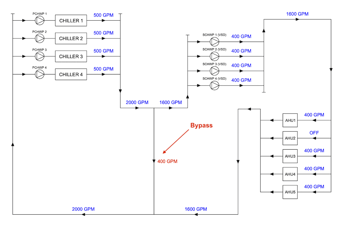
From the above diagram, the air handling units (AHUs) demand a total chilled water flow rate of 1600 GPM. In response, the variable-speed secondary chilled water pumps reduce their speed to match the demand.
However, the primary circuit can’t reduce the chilled water flow rate because the primary chilled water pumps are fixed-speed pumps. If one of the pumps and its associated chiller is turned off, the chilled water flow rate produced will drop to 1500 GPM which is not sufficient given the demand.
As a result, all chillers have to maintain operation and a surplus of 400 GPM chilled water will flow back to the chillers via the bypass line.
But, if the chilled water flow rate in the bypass line is more than 500 GPM, one of the chillers can be turned off.
The staging of the chiller can be done by comparing two separate flow meters, one at the primary circuit and one at the secondary circuit. The flow difference between the two flow meters is equivalent to the flow in the bypass line.
Such a chiller control system is also known as flow-based control, as opposed to temperature-based control.
It is important to design the bypass line appropriately to prevent too much chilled water from flowing through the bypass line and causing chilled water short cycling which can lead to all sorts of performance issues.
On a side note, if you want to quickly learn about chilled water system, you can get my Chilled Water System (eBook). If you’re into design, you can enroll in my Chilled Water System Design Course where I teach you various design procedures with tons of examples.
Chilled Water System Design Course
Learn how to design a chilled water system with AHU/FCU selection, chiller sizing, cooling tower sizing, pump sizing, piping design, ductwork design and more.
2. Maintaining Pump Minimum Flow
In the same primary-secondary chilled water system, the secondary chilled water pumps are variable-speed pumps, meaning their pump speed can be changed.
However, with variable speed, there is a minimum flow requirement.
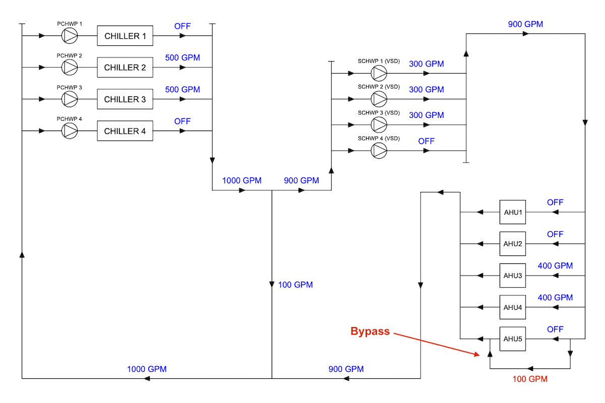
Assume that each of the secondary chilled water pumps has a minimum flow of 300 GPM, if the demand for chilled water is 800 GPM as shown in the above diagram, the minimum amount of chilled water can be circulated in the secondary circuit is 900 GPM, which means there is a surplus of 100 GPM.
Hence, a bypass is needed at the air handling unit (AHU) to allow the extra chilled water to flow through the circuit. The bypass can be accomplished using a 3-way valve.
It is important to size the secondary chilled water pumps appropriately based on the building’s load profile to ensure that the demand for chilled water can be met during low-load conditions.
At the same time, a proper number of bypasses must be allocated to ensure the minimum flow of the variable-speed pumps can be met.
3. Maintaining Chiller Minimum Flow
In the primary-variable chilled water system, the chilled water pumps are variable-speed pumps.
There are no secondary chilled water pumps.
When the demand for chilled water drops, the variable-speed chilled water pumps adjust the chilled water flow rate accordingly.
However, with variable speeds, the pumps have a minimum flow requirement.
On top of that, the chillers also have a minimum flow requirement. If the chilled water flow rate is too low, the chiller evaporator may freeze.
Therefore, a chiller minimum flow bypass is needed.
If the demand drops beyond the minimum flow of the chiller, a bypass valve will open to allow the extra chilled water to flow back to the chiller.
4. Condenser Water Temperature Control
Although water-cooled chillers are more efficient when operating under low condenser water temperatures, the limitation is usually somewhere around 15°C (59°F).
If the condenser water supply temperature is too low, a cooling tower bypass is needed.
A bypass line can be installed at the chiller condenser water outlet to circulate the condenser water back to the chiller to quickly increase the condenser water temperature.
This bypass is usually needed in cold places where the environment itself can cool the condenser water at the basin of the cooling tower to a temperature beyond the chiller’s limitation.
5. Cooling Coil Damage Prevention
Upon the completion of the chilled water pipe installation and before commissioning the chilled water system, the pipes have to be flushed to get rid of dirt and debris inside the pipes.
On the other hand, cooling coils are made of thin copper which can be easily damaged if dirt and debris are allowed to flow through the coils.
Therefore, a bypass is needed at each AHU and FCU to exclude the cooling coils from the flushing process.
Conclusion
Bypass is a simple mechanism to ensure the chilled water system functions properly. However, it must be designed properly as many chilled water systems are having performance issues due to inappropriate bypass sizing. On top of that, issues due to bypass size are difficult to identify.
Once again, you can get my Chilled Water System (eBook) to quickly learn more about chilled water system. But, if you want to learn how to design a chilled water system from start to end, I encourage you check out my Chilled Water System Design Course.
Chilled Water System Design Course
Learn how to design a chilled water system with AHU/FCU selection, chiller sizing, cooling tower sizing, pump sizing, piping design, ductwork design and more.
If you have anything to add (or ask) about this topic, leave a comment down below!


