Hydronic Balancing Basics (Chilled Water System)
Hydronic balancing is important to the efficiency and effectiveness of chilled water system. However, many engineers find it very difficult to understand. So, I did some intensive studies.
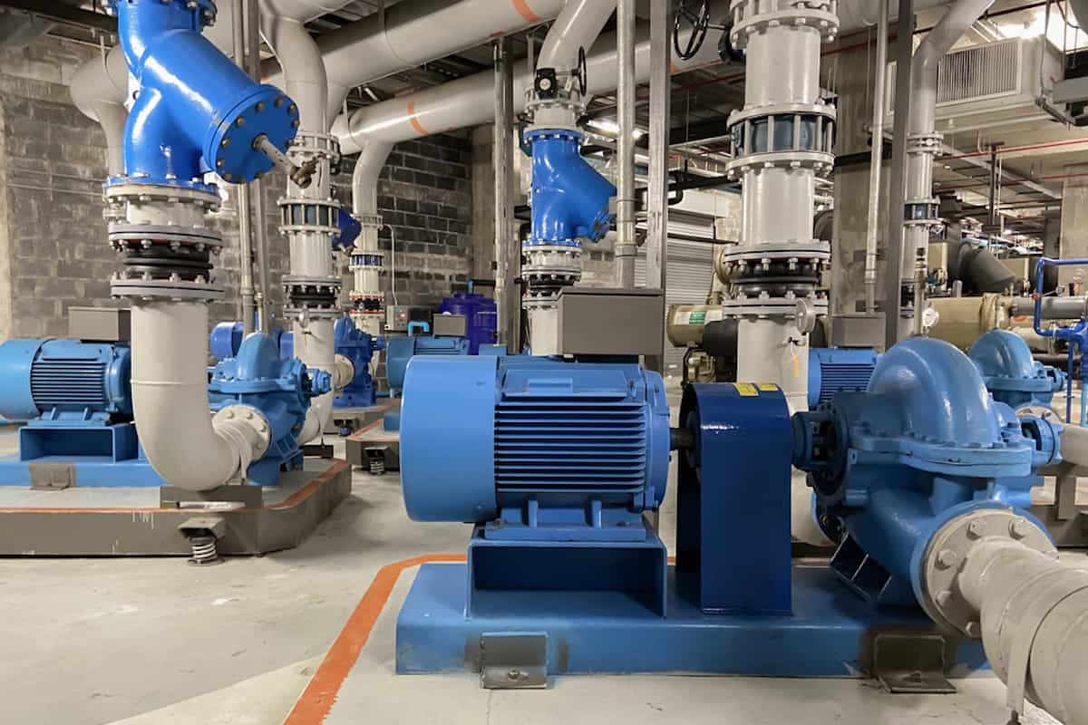
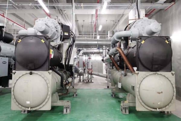
Liquid water is used as the heat transfer medium in chilled water system. Using the refrigeration cycle, chillers produce chilled water and chilled water pumps circulate the chilled water to air handling units (AHUs) and fan coil units (FCUs) in a closed loop piping system.
Then, the chilled water flows through the cooling coil of AHUs and FCUs thereby making the surface of the cooling coil icy cold. Meanwhile, AHUs and FCUs circulate indoor air through their respective cooling coil to produce cold air and thus, cool the room.
Why Hydronic Balancing is Needed?
In order for the AHUs and FCUs to cool properly, manufacturers specified the required amount of chilled water flow rate based on the cooling capacity. In other words, each unit has its required chilled water flow rate.
As mentioned earlier, the chilled water is distributed by the chilled water pumps. However, AHUs and FCUs near the chilled water pumps tend to have a higher water flow rate than the AHUs and FCUs located far away from the chilled water pumps.
Consequently, AHUs and FCUs installed far away from the chilled water pumps may not receive sufficient chilled water flow rate and thus, they may not able to provide sufficient cooling.
So, hydronic balancing is extremely important in chilled water system to ensure that every AHU and FCU is receiving sufficient chilled water flow rate as per the design and requirement.
Why is Causing Hydronic Imbalance?
The reason why every AHU and FCU receives a different amount of chilled water flow rate is because of different quantities of pipe lengths, pipe fittings, valves and the AHU and FCU itself. In other words, different pressure drop causes different amount of chilled water flow rate.
The difference between the pressure before and after a valve is called valve pressure drop. The same applies to pipe fittings and the AHU and FCU itself. AHUs and FCUs also have their own pressure drop and it is specified by the manufacturer.
Similarly, when chilled water moves through a length of pipe, it losses some of its energy due to friction. Hence, there is a pressure drop.
Pressure drop is always a result of two different pressures, before and after something like a valve, fitting or pipe. So, if a valve has a pressure drop of 0.5 kPa, it means that the valve is “blocking” against the water by 0.5 kPa of pressure thereby slowing down the water flow rate.
The key to balancing the hydronic system is to equalize the pressure drop for each and every AHU and FCU. If the pressure drop across each AHU and FCU is the same, all AHUs and FCUs will have equal chilled water flow rate.
Let’s take a look at the following example:
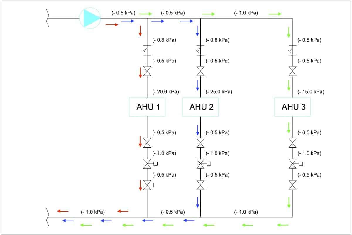
The above diagram shows three different circuits for AHU 1, AHU 2 and AHU 3. Their respective pressure drop can be calculated by adding the individual pressure drop along their respective circuit.
For instance, if we follow the red line, the pressure drop across AHU 1 is (-0.5 kPa) + (-0.8 kPa) + (-0.5 kPa) + (-20.0 kPa) + (-0.5 kPa) + (-1.0 kPa) + (-0.5 kPa) + (-1.0 kPa) = -24.8 kPa.
So, the pressure drop of all three circuits are shown in the below table:
| Circuit | Total Pressure Drop |
|---|---|
| AHU 1 | -24.8 kPa |
| AHU 2 | -30.8 kPa |
| AHU 3 | -22.8 kPa |
From the total pressure drop, we know that AHU 3 will have the most amount of chilled water flow rate because the pressure drop is lower and AHU 2 will have the least amount of chilled water flow rate because the pressure drop is higher.
On a side note, if you want to quickly learn about chilled water system, you can get my Chilled Water System (eBook). If you’re into design, you can enroll in my Chilled Water System Design Course where I teach you various design procedures with tons of examples.
Chilled Water System Design Course
Learn how to design a chilled water system with AHU/FCU selection, chiller sizing, cooling tower sizing, pump sizing, piping design, ductwork design and more.
Why Balancing Valves are Necessary?
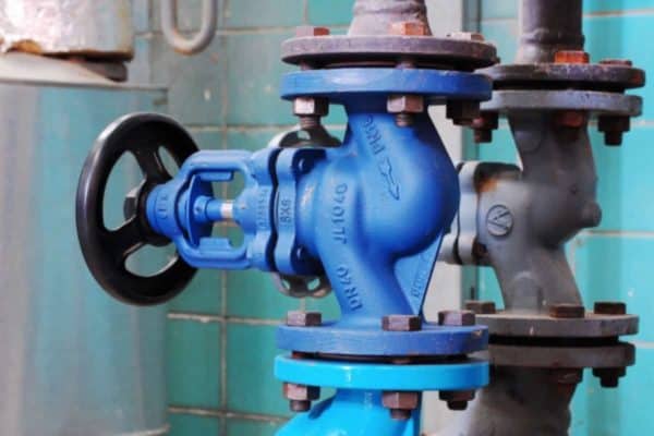
Since valves are essential, we can’t reduce the total pressure drop of AHU 2 to match with AHU 1 and AHU 3. However, we can install a balancing valve in each circuit to create an extra pressure drop thereby increasing the total pressure drop to balance all three circuits.
Let’s bring up the example again:
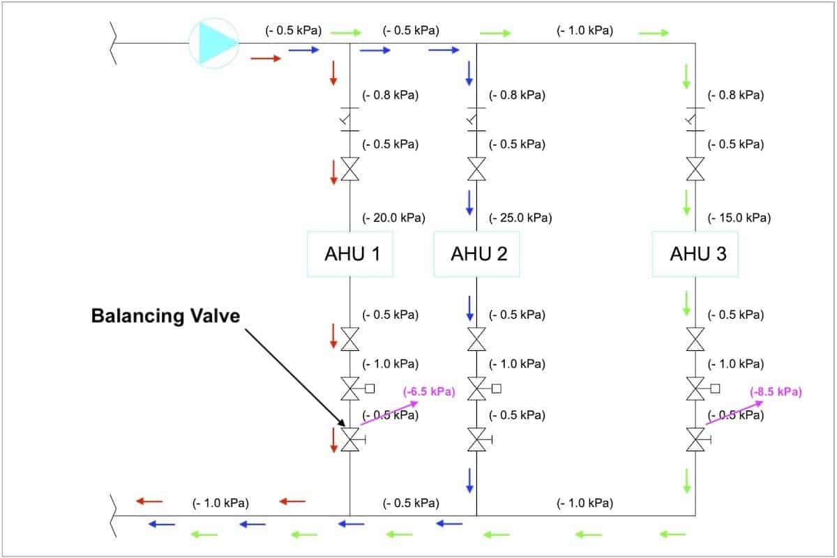
Previously, there is a balancing valve installed in each circuit but the balancing valve is fully opened which yields a pressure drop of -0.5 kPa.
Now, we can close the respective balancing valve by a certain degree thereby increasing its pressure drop to the desired level.
In the above diagram, all three circuits now are balanced at a total pressure drop of 30.8 kPa.
| Circuit | Total Pressure Drop | Balancing Valve | New Total Pressure Drop |
|---|---|---|---|
| AHU 1 | -24.8 kPa | -6 kPa | -30.8 kPa |
| AHU 2 | -30.8 kPa | No Change | -30.8 kPa |
| AHU 3 | -22.8 kPa | -8 kPa | -30.8 kPa |
Therefore, all three AHUs will be receiving the same amount of chilled water flow rate.
The above example does not represent the actual piping connections and pressure drop values but they are close to reality. The intention here is to simplify things for better understanding.
Nevertheless, it explains why we install a balancing valve and how the balancing valve helps to balance the chilled water flow rate.
Now, if we don’t want to install a balancing valve for whatever reasons, we can increase the respective pipe length thereby adding more pressure drop to achieve the same result. Such a method is known as the reverse return piping system.
Problems with Manual Hydronic Balancing
The example I show above is assumed that the modulating valve (control valve) of the AHUs are fully opened. Hence, such a balancing method is also known as static hydronic balancing.
In practice, the modulating valve of AHUs will close and open at a certain degree to control the amount of chilled water flowing through their cooling coil thereby controlling the cooling capacity to ensure that the room is neither undercooled nor overcooled.
As you might have guessed already, once the modulating valves start to move, the hydronic system becomes imbalanced again because it was balanced based on fully-opened modulating valves.
So, we need to revisit each balancing valve again and again during operation to try to tune it until the system is fairly balanced, sort of like a trial and error method.
However, in the book Total Hydronic Balancing by Robert Petitjean, the Compensation method is recommended to balance the hydronic system such that each balancing valve is only required to be set once and for all.
In short, the Compensation method uses a reference valve and a partner valve to isolate the total pressure drop within a circuit that was balanced before. Hence, changes in other circuits in the future will not affect the chilled water flow rate of the previously balanced circuits.
Modern Hydronic Balancing Method
Modern chilled water system use pressure-independent balancing control valves (PIBCVs). Manual balancing valves and the separated control valves are no longer needed. Both valves are combined together into one precise flow control valve.
With PIBCVs, we only need to calculate the preset value once during the selection of the valve. Then, when the hydronic system operates, each PIBCV can increase/decrease its pressure drop automatically thereby balancing the entire system all the time.
Meanwhile, the PIBCVs also regulate the amount of chilled water flow into their respective AHU or FCU. Because they are balanced all the time, they deliver a precise amount of chilled water and therefore, all AHUs and FCUs are always operating at optimal performance.
Back in the days before the invention of PIBCVs, contractors are having a hard time trying to balance the hydronic system. It is both time and energy-consuming. Hence, many contractors only tune the hydronic system as much as necessary such that as long as nobody complains about the cooling, it’s considered done.
Nowadays, hydronic balancing is getting easier thanks to pressure-independent balancing control valves. Not only the commissioning process is quicker but the hydronic system is running more efficiently now.
Once again, you can get my Chilled Water System (eBook) to quickly learn more about chilled water system. But, if you want to learn how to design a chilled water system from start to end, I encourage you check out my Chilled Water System Design Course.
Chilled Water System Design Course
Learn how to design a chilled water system with AHU/FCU selection, chiller sizing, cooling tower sizing, pump sizing, piping design, ductwork design and more.
If you have anything to add (or ask) about this topic, leave a comment down below!


