How to Calculate Chilled Water Pump Head?
Pump head is an essential parameter for chilled water pumps as well as condenser water pumps. It determines if the pumps are able to deliver the required water flow rate. So, how do you calculate the required pump head?
To calculate chilled water pump head, first determine the total water flow required. Then, identify the farthest equipment on the piping system. Next, find the total head loss of the longest piping loop. Finally, calculate the required pump head using the Hazen-Williams Equation.
I, unfortunately, did not have the chance to work on the detailed design of chilled water pumps and chilled water piping systems. Hence, I seek help from one of my friends who had done pump head calculations before.
There are a few ways to calculate pump head but the one that I find quite easy to understand and implement is by using the equivalent pipe length method with the Hazen-Williams Equation.
Many HVAC consultants and contractors use such a method to calculate pump head. Furthermore, some pump suppliers also use this method to calculate and select the appropriate pump.
So, without further ado, let’s get started.
What is Pump Head?
To learn how to calculate pump head, it is important to understand the basics of pump head.
Pump head can be viewed as the strength of a pump to overcome the friction caused by pipes, valves and fittings. If a pump doesn’t have a sufficient pump head, it won’t be able to deliver the water flow rate as promised.
The water flow rate (eg: gpm, m3/s, L/s) of a pump is always stated based on a given pump head.
For example, when a pump has a water flow rate of 1000 gpm at 20 meters of head, it means that the pump is able to deliver 1000 gpm of water given that the total head loss is 20 meters.
Imagine when you go to the gym. A guy says he can do 10 reps. But, there is no context to it. What is 10 reps? He must also let you know 10 reps at what weight. For instance, 100 lbs. So, he can do 10 reps at 100 lbs.
The same applies to chilled water pumps and condenser water pumps and basically any pumps. A pump delivers a certain amount of water flow after it overcame all of the friction or technically known as head loss.
The pipe itself, valves and pipe fittings tend to slow down the flow of water. They impose resistance on the flowing water and such resistance is known as head loss.
Head loss can be expressed in many different units such as meter, kPa and psi. For simplicity, I’ll use meter as the primary unit for head loss.
When the head loss of a valve or pipe fitting is expressed in meter, it is equivalent to the head loss of straight pipe in meter. For instance, if a valve has a head loss of 0.35 meter, it has the same resistance (head loss) as a 0.35 meter long straight pipe.
On a side note, if you want to quickly learn about chilled water system, you can get my Chilled Water System (eBook). If you’re into design, you can enroll in my Chilled Water System Design Course where I teach you various design procedures with tons of examples.
Chilled Water System Design Course
Learn how to design a chilled water system with AHU/FCU selection, chiller sizing, cooling tower sizing, pump sizing, piping design, ductwork design and more.
Hazen-Williams Equation
There are a few ways to calculate pump head and the Hazen-Williams Equation is one of the methods which I find relatively easier to understand and implement.
The Hazen-Williams Equation is also suggested by ASHRAE as one of the methods to calculate pump head. However, it is applicable to water only which is not a problem for HVAC chilled water pumps and condenser water pumps.
The Hazen-Williams Equation for piping head loss is as follow:
HL = (10.67 x Q1.852) ÷ (C1.852 x D4.8704)
where,
HL = head loss per meter
Q = water flow rate, m3/s
C = Hazen-Williams coefficient, (120 for Steel)
D = pipe internal diameter, m
The Hazen-Williams coefficient is normally at 120. However, if the pipe is dirty, we can use 110. Otherwise, if the pipe is extremely smooth, the value can be 150.
Now, based on the Hazen-Williams Equation, let’s take a look at an example of how to calculate pump head for chilled water pumps (closed loop).
Chilled Water Pump Head Calculation
The pump head calculation for chilled water pumps is slightly different from condenser water pumps because the former is in a closed loop while the latter is in an open loop.
For chilled water pumps, the calculation involved much more elements and thus, I use it as an example and later, you’ll also understand how to calculate for condenser water pumps.
Preliminary
Before we proceed to calculate the pump head, there are a few things to be done beforehand:
- The piping system layout has been designed.
- All AHUs and FCUs have been selected.
- All valves have been designed and located.
Basically, you need to finish like 99% of the chilled water piping system design. The last thing you need to do is to calculate the total head loss of the system and then, select the suitable pump to deliver the required water flow rate.
With that said, the following is a step-by-step process on how to calculate chilled water pump head:
1. Calculate the Total Water Flow Required
As mentioned earlier, you need to complete the piping layout including pipe sizing and equipment selection (FCU/AHU models).
Once you have that, sum up the water flow rate of each AHU and FCU to calculate the total water flow required for the pump.
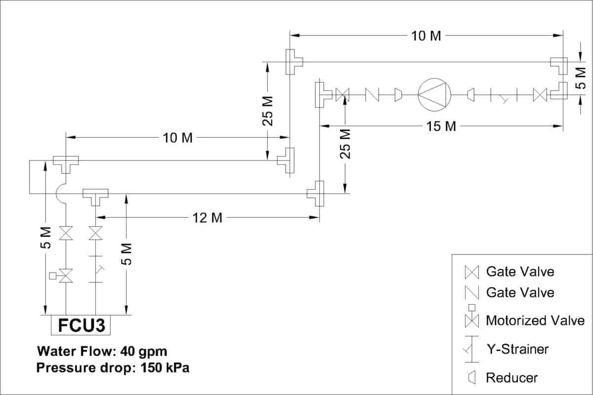
Below diagram is a simplified system I’ll be using as an example for the pump head calculation:
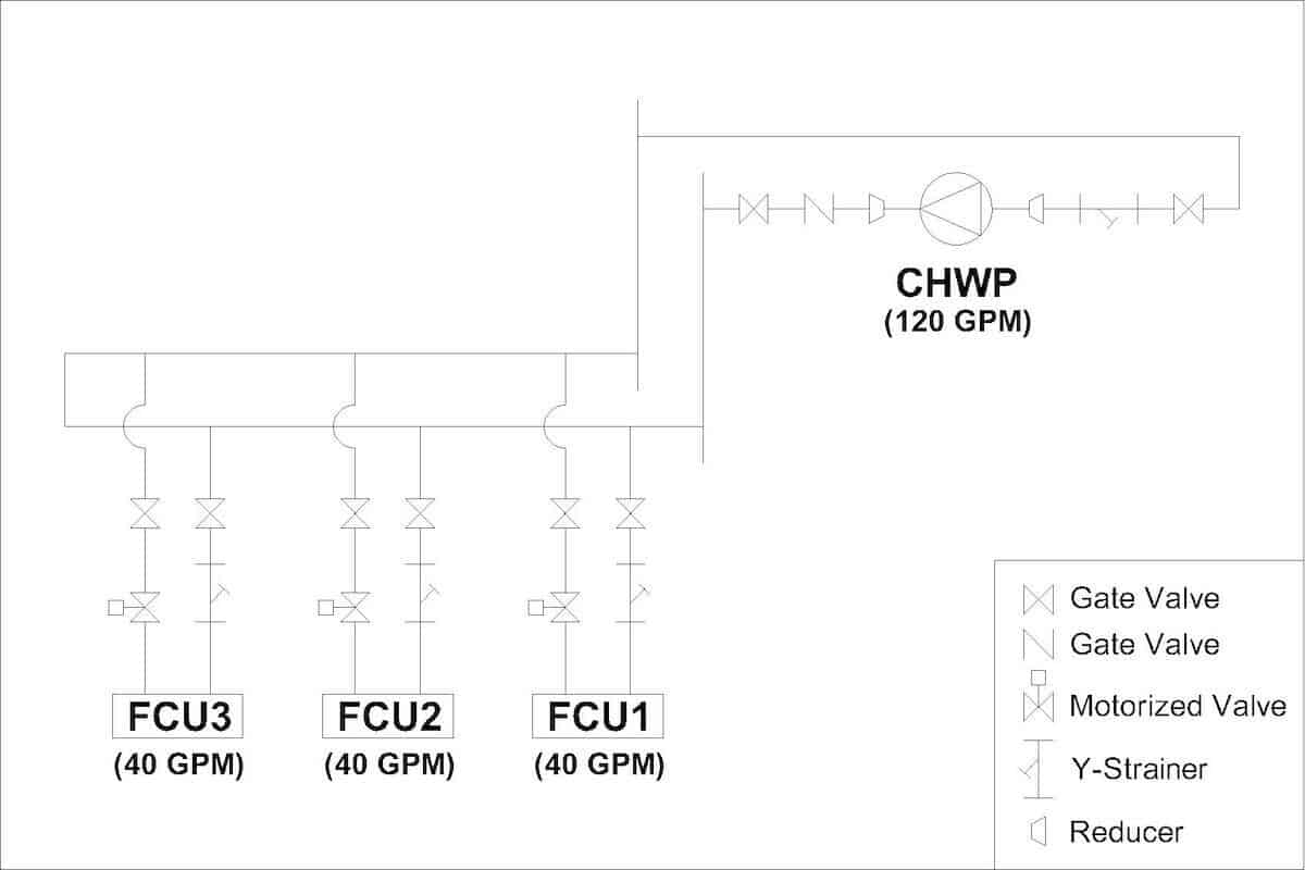
Assume that I have 3 FCUs in a closed loop with a pump. The first thing to do is to calculate how much water flow is required for the pump.
Here, it is important that you identify the loop or equipment that is going to be served by the pump. Carefully separate out others that are not responsible by the pump.
From the above diagram, each FCU requires 40 gpm (0.002524 m3/s) of water flow rate. So, the total water flow required to be delivered by the pump is 120 gpm (0.007571 m3/s).
2. Identify the Farthest Air Conditioning Unit
A pump must have enough strength to push through all resistances and deliver water to the farthest FCU or AHU. Hence, the next step is to identify the farthest FCU or AHU.
After that, it is better to label all the pipe fittings along the way so that you don’t miss out, especially if you have never done this before, particularly the Tee fittings.
Then, you also need to find out the water pressure drop of the associated equipment along the way. Usually, for equipment like AHUs and FCUs, you can find the water pressure drop in the datasheet provided by the manufacturer.
With that said, let’s continue my example:
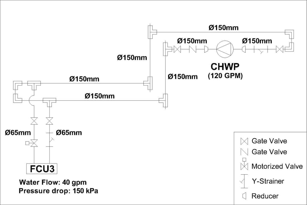
As you can see, I deleted unrelated FCUs to make it clearer. Then, I draw out the Tee and elbow fittings so that I don’t miss them out. Also, remember to include pipe reducers.
From my example, the farthest FCU has a water pressure drop of 150 kPa (15.3 m of head). You can use any online converter to convert kPa to meter of head.
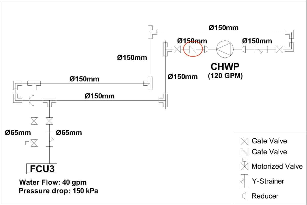
3. Find the Equivalent Pipe Length
Now, we need to identify the pressure drop of individual valves and pipe fittings expressed in equivalent pipe length (meter of head).
Sometimes, you can get such information from the manufacturer of the selected valves and pipe fittings.
However, if you can’t get the information or you haven’t selected the manufacturer, you can refer to the valve & fittings loss tables by Carrier which you can download for free here.
Now, let’s take a closer look at how to use the equivalent length tables to find the equivalent pipe length.
a) Equivalent Pipe length Chart
For example, the 150 mm (6″) check valve at the discharge line of the pump is equivalent to 60 ft (18.29 m) of straight pipe length based on the table by Carrier.
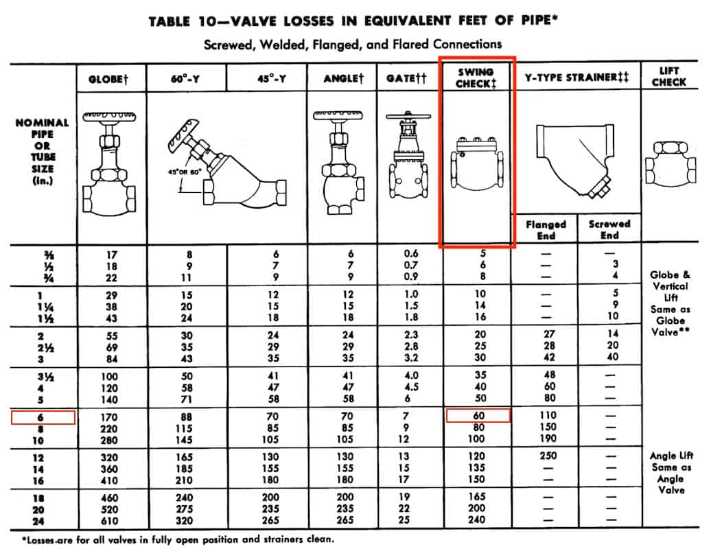
However, not all valve types can be obtained from the Carrier table, especially new valves. So, you may still need to find other resources or refer to the manufacturer for accurate numbers.
For common valves like those listed in the table, it is good enough.
b) Equivalent Pipe Length of Individual Valves & Fittings
So, by repeating the same process, we have the following for valves and pipe fittings:
| Components | Size | Equivalent Length |
|---|---|---|
| Check Valve | 150 mm (6″) | 60 ft (18.29 m) |
| Gate Valve | 150 mm (6″) | 7 ft (2.13 m) |
| Y-Strainer | 150 mm (6″) | 110 ft (33.53 m) |
| Tee Fitting | 150 mm (6″) | 30 ft (9.14 m) |
| 90° Elbow | 150 mm (6″) | 16 ft (4.88 m) |
| Reducer | 150 mm (6″) | 16 ft (4.88 m) |
| Gate Valve | 65 mm (2-1/2″) | 2.8 ft (0.85 m) |
| Y-Strainer | 65 mm (2-1/2″) | 28 ft (8.53 m) |
| Motorized Valve | 65 mm (2-1/2″) | 69 ft (21.03 m) |
c) Total Equivalent Pipe Length of Valves & Fittings
The above is the equivalent length for a single valve and fitting. Now, let’s add them up with the quantity. Here, we need to calculate each size separately due to the Hazen-Williams Equation later.
For 150 mm (6″) valves and fittings:
| Components | Qty | Total Equivalent Length |
|---|---|---|
| Check Valve 150 mm (6″) | 1 | 60 ft (18.29 m) |
| Gate Valve 150 mm (6″) | 2 | 14 ft (4.26 m) |
| Y-Strainer 150 mm (6″) | 1 | 110 ft (33.53 m) |
| Tee Fitting 150 mm (6″) | 6 | 180 ft (54.84 m) |
| 90° Elbow 150 mm (6″) | 4 | 64 ft (19.52 m) |
| Reducer 150 mm (6″) | 2 | 32 ft (9.76 m) |
| Grand Total | 16 | 460 ft (140.2 m) |
For 65 mm (2-1/2″) valves and fittings:
| Components | Qty | Total Equivalent Length |
|---|---|---|
| Gate Valve 65 mm (2-1/2″) | 2 | 5.6 ft (1.7 m) |
| Y-Strainer 65 mm (2-1/2″) | 1 | 28 ft (8.53 m) |
| Motorized Valve 65 mm (2-1/2″) | 1 | 69 ft (21.03 m) |
| Grand Total | 4 | 102.6 ft (31.26 m) |
d) Total Equivalent Pipe Length of Straight Pipes
Once we have the total equivalent length for valves and fittings, it’s time to measure and include the straight pipe length:
For straight pipes:
| Pipe Size | Pipe Length |
|---|---|
| 150 mm (6″) | 334.65 ft (102 m) |
| 65 mm (2-1/2″) | 32.81 ft (10 m) |
So, the total equivalent pipe length of 150 mm (6″) valves and fittings is 460 ft (140.2 m) and the total length of 150 mm (6″) straight pipes is 334.65 ft (102 m). Hence, the grand total for 150 mm (6″) is 794.65 ft (242.2 m).
Meanwhile, the total equivalent pipe length of 65 mm (2-1/2″) valves and fittings is 102.6 ft (31.26 m) and the total length of 65 mm (2-1/2″) straight pipes is 32.81 ft (10 m). Hence, the grand total for 65 mm (2-1/2″) is 135.41 ft (41.26 m).
4. Calculate the Total Head Loss
Now, let’s bring back everything that we’ve calculated so far:
- Total water flow: 120 gpm (0.007571 m3/s)
- Total equivalent length for 150 mm (6″): 794.65 ft (242.2 m)
- Total equivalent length for 65 mm (2-1/2″): 135.41 ft (41.26 m)
- Hazen-Williams coefficient: 120
From there, we can calculate the total head loss using the Hazen-Williams Equation as follow:
150 mm (6″) Valves & Fittings Head Loss
Using the Hazen-Williams Equation for 150 mm (6″) pipe size:
HL = (10.67 x Q1.852) ÷ (C1.852 x D4.8704)
HL = (10.67 x 0.0075711.852) ÷ (1201.852 x 0.154.8704)
HL = 1.81 x 10⁻³
Now, this HL is head loss per meter. To find the head loss, multiply it by the total length of straight pipes, valves and fittings:
Head Loss = HL x Total Equivalent Length
Head Loss = 1.81 x 10-3 x 242.2
Head Loss = 0.44 m
65 mm (2-1/2″) Valves & Fittings Head Loss
Using the Hazen-Williams Equation for 65 mm (2-1/2″) pipe size:
HL = (10.67 x Q1.852) ÷ (C1.852 x D4.8704)
HL = (10.67 x 0.0075711.852) ÷ (1201.852 x 0.0654.8704)
HL = 0.107
Head Loss = HL x Total Equivalent Length
Head Loss = 0.107 x 41.26
Head Loss = 4.42 m
So, the total head loss from pipes, valves and fittings is 0.44 + 4.42 = 4.86 m. Let’s give it a 20% safety factor and the resulted head loss is 5.83 m.
Equipment Pressure Drop & Total Head Loss
Now, remember that the pressure drop of the FCU3 is 150 kPa (15.3 m), let’s include that and find the total head loss:
Total Head Loss = 5.83 + 15.3
Total Head Loss = 21.13 m (69.33 ft)
So, the total head loss is 21.13 m (69.33 ft) which means that we need to select a pump that is capable of delivering 120 gpm (27.25 m3/hr) of water at 21.13 m (69.33 ft) of head.
5. Select the Pump
Usually, we let the pump supplier to select a suitable pump based on the required water flow rate and head. Nonetheless, the pump selection process is relatively easy.
First, you need to obtain the pump curve of various pump models from your preferred manufacturer(s). Then, just match the water flow rate and head to find the best model.
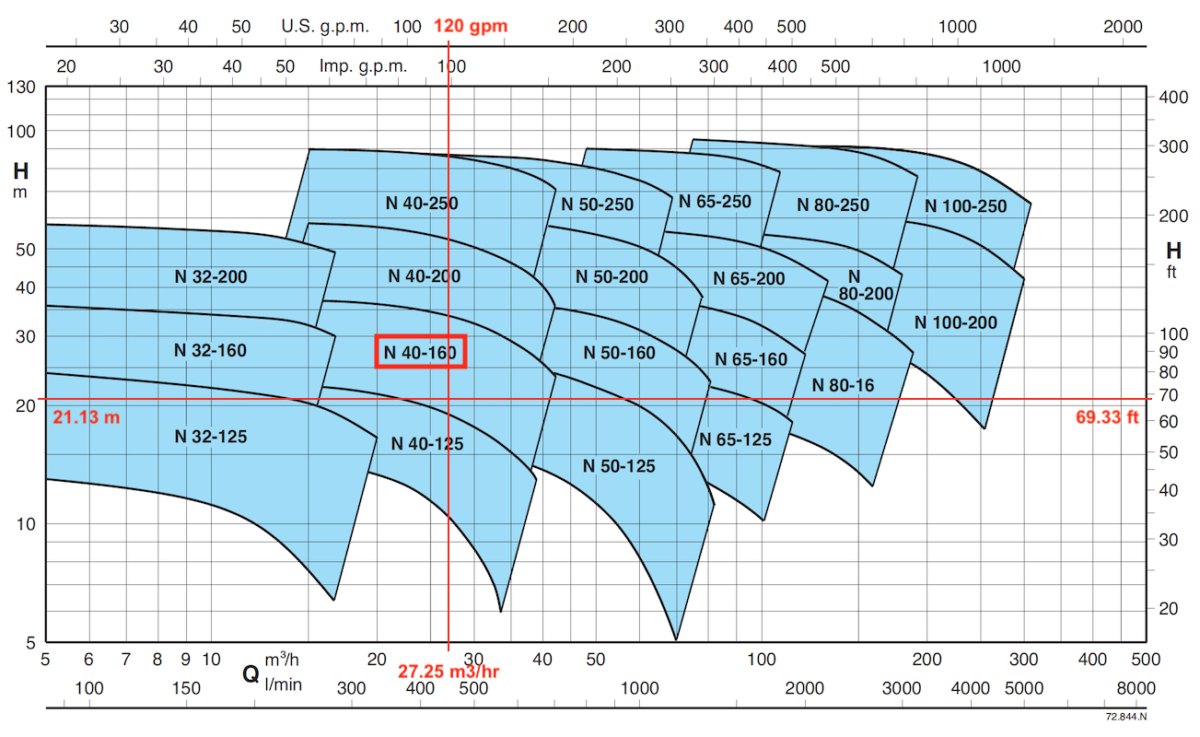
So, if I take Calpeda end suction pump, the N40-160 model is suitable for 120 gpm at 21.13 m of head. That’s how you can do it from calculating the total head loss to selecting the suitable pump.
Final Thought
The above example is a simplified version for you to understand the pump head calculation process. In reality, chilled water systems are much more complicated.
Hence, dividing the calculation process into several sections is a good idea to keep everything on track, especially when you need to go back and make changes that do happen quite frequently.
Once again, you can get my Chilled Water System (eBook) to quickly learn more about chilled water system. But, if you want to learn how to design a chilled water system from start to end, I encourage you check out my Chilled Water System Design Course.
Chilled Water System Design Course
Learn how to design a chilled water system with AHU/FCU selection, chiller sizing, cooling tower sizing, pump sizing, piping design, ductwork design and more.
If you have anything to add (or ask) about this topic, leave a comment down below!